Manufacturing Intern
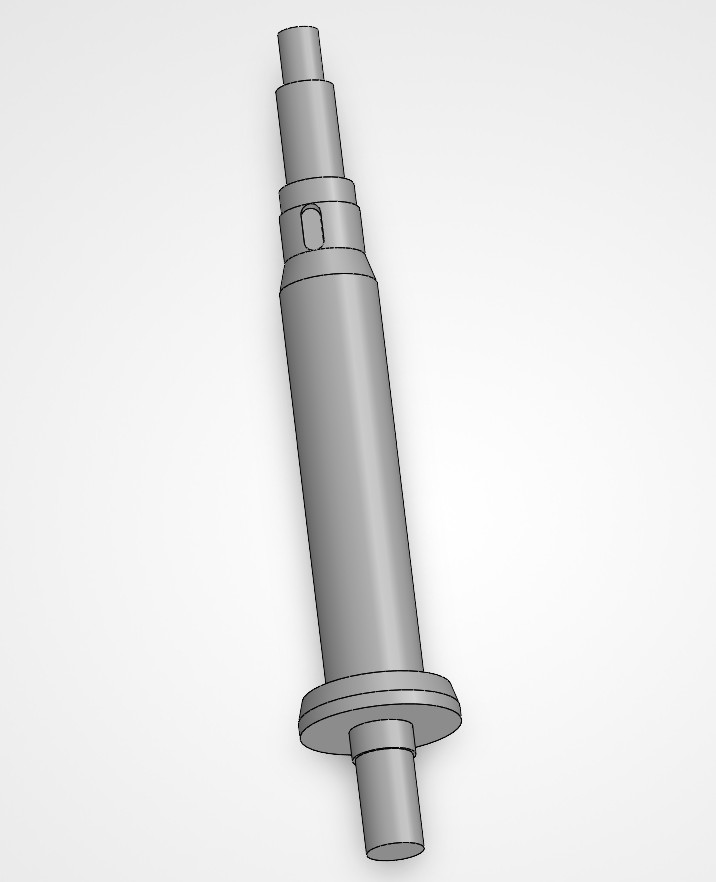
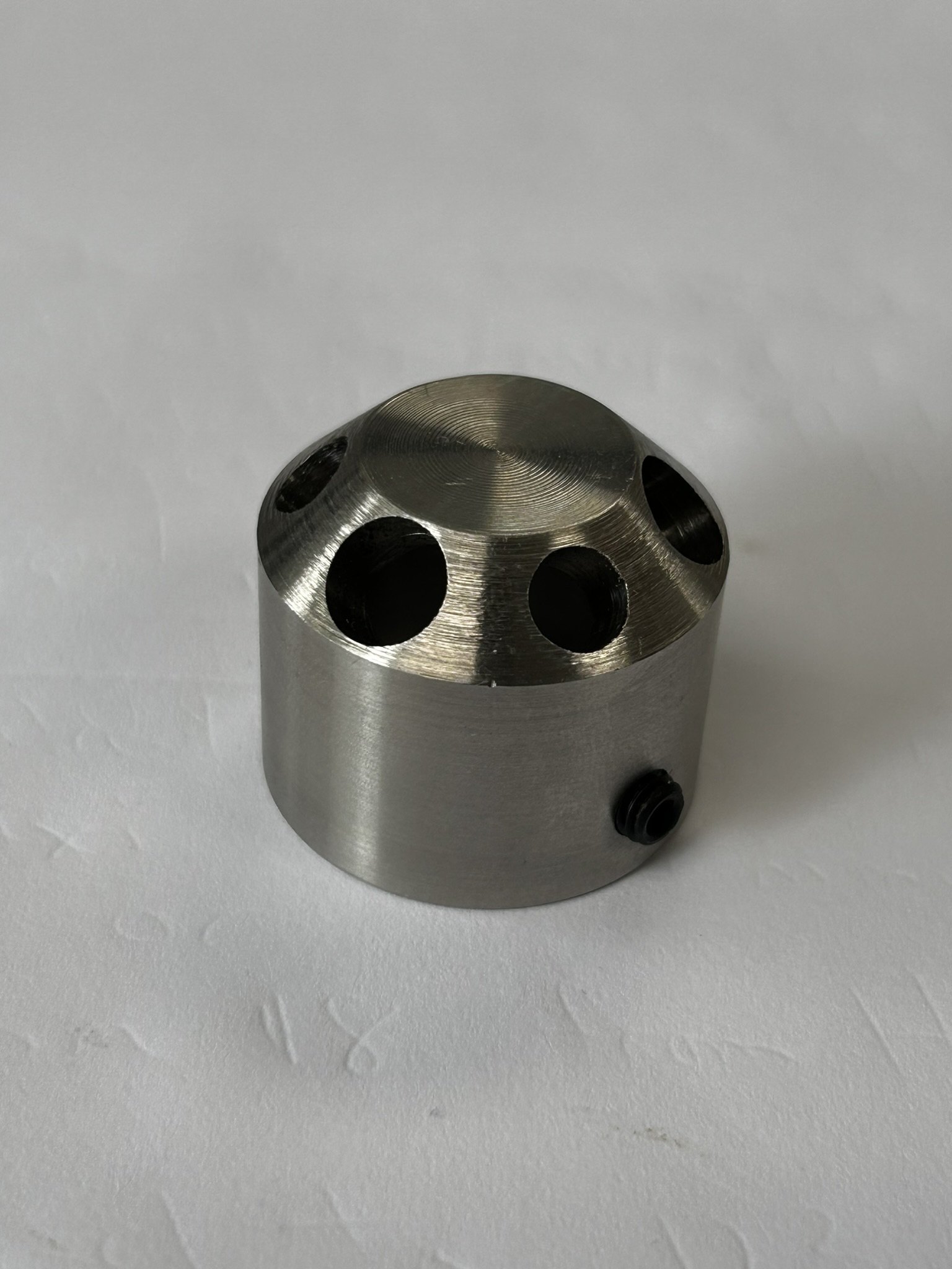
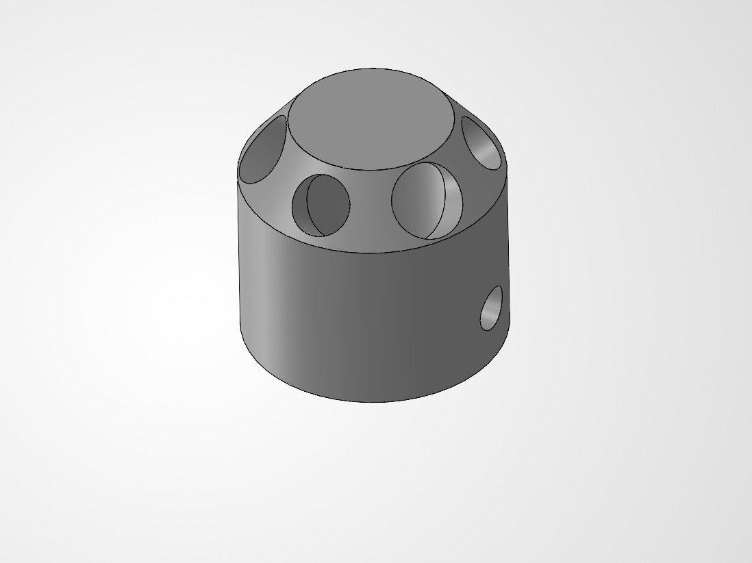
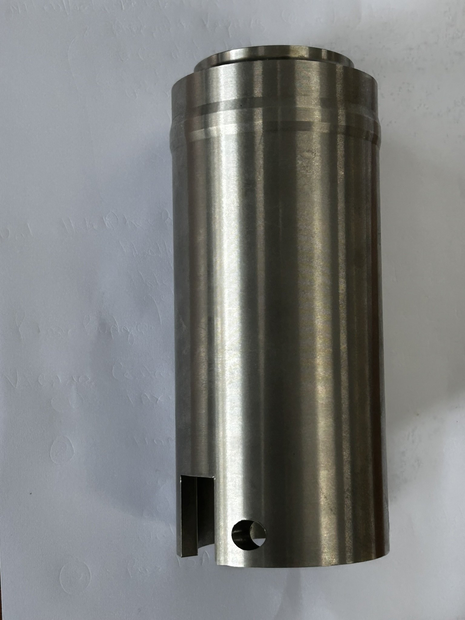
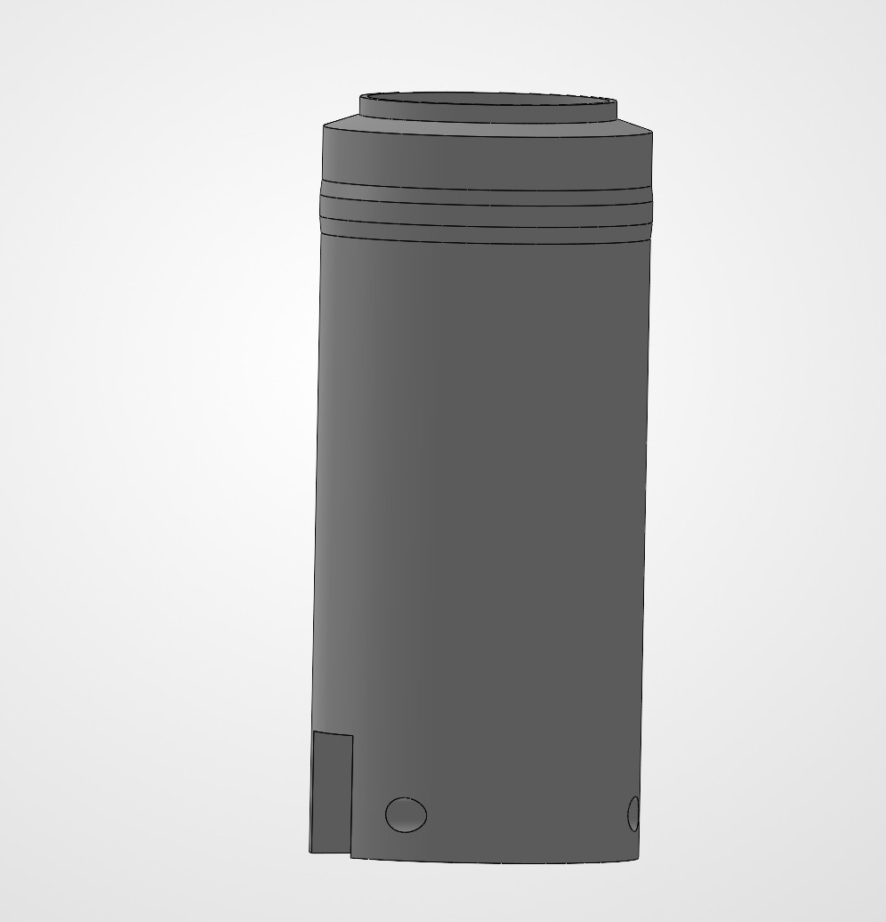
- Produced dimensioned CAD models and manufacturing drawings from existing physical components in SolidWorks, reconstructing geometry, tolerances, and GD&T callouts for legacy parts lacking documentation; drawings were released to production and used to manufacture parts.
- Designed and deployed the shop’s production quality-control system, replacing a paper-based inspection workflow with enforced dimensional verification that hard-stops a job when a reading falls out of spec, staging inspection from casting to first-article to QA-approved-to-ship with blind re-measurement; used daily by 6 machinists across ~10 work orders per day.
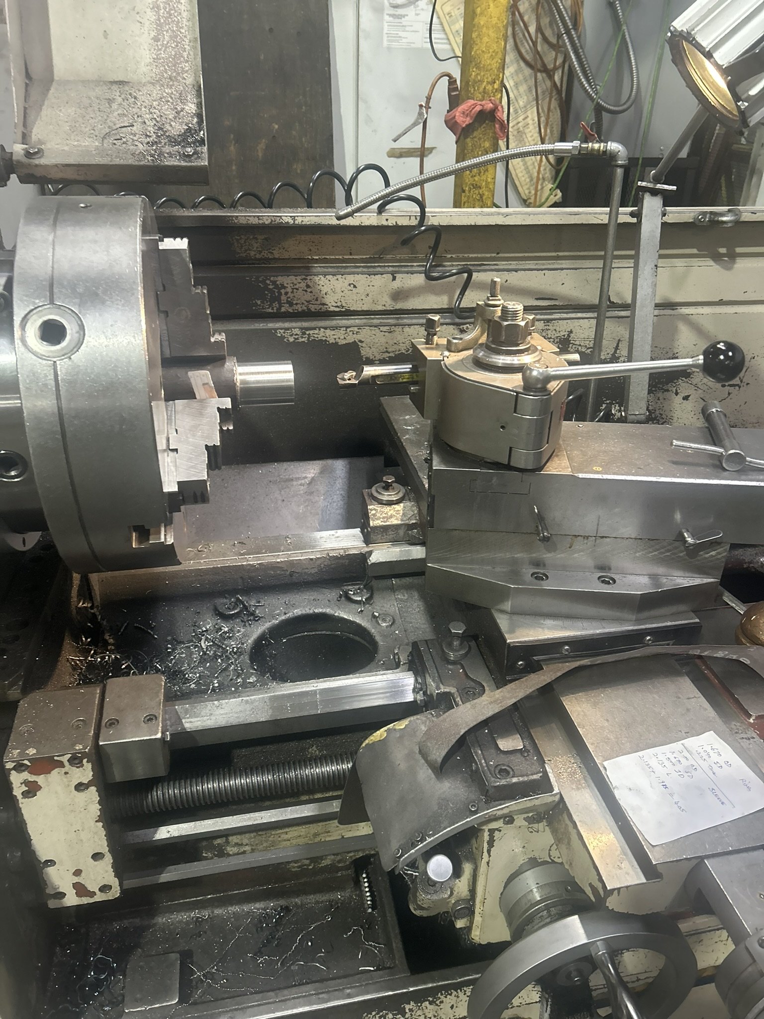
- Operated manual lathes independently across the full job scope, interpreting drawings, planning operation sequence, selecting tooling and speeds/feeds, and performing in-process dimensional inspection to hold specified tolerances.
- Manufactured precision components on CNC mills and lathes, frequently operating 2–3 machines concurrently and holding tolerances as tight as ±0.001 in.; proposed revised CAD designs of existing components to improve manufacturability and reduce machining operations.
Sleeved Roll Training Assembly
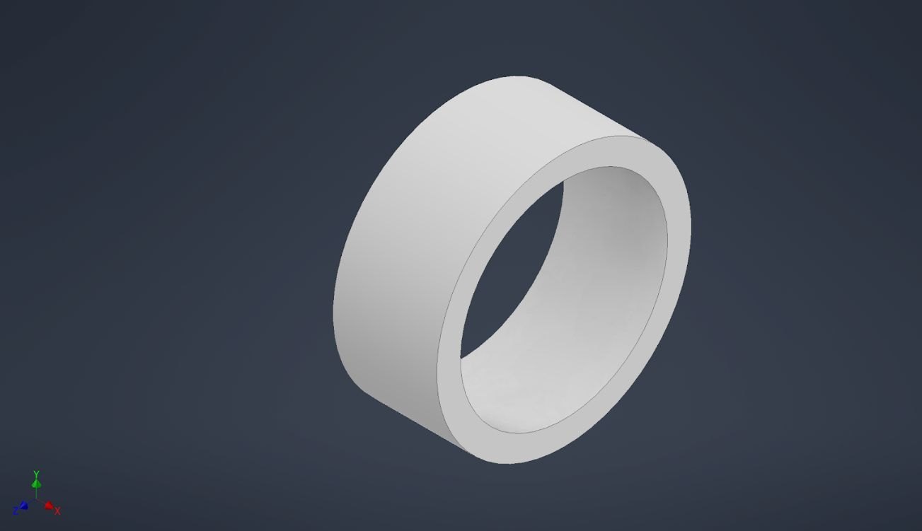
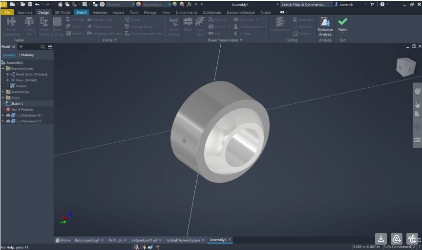
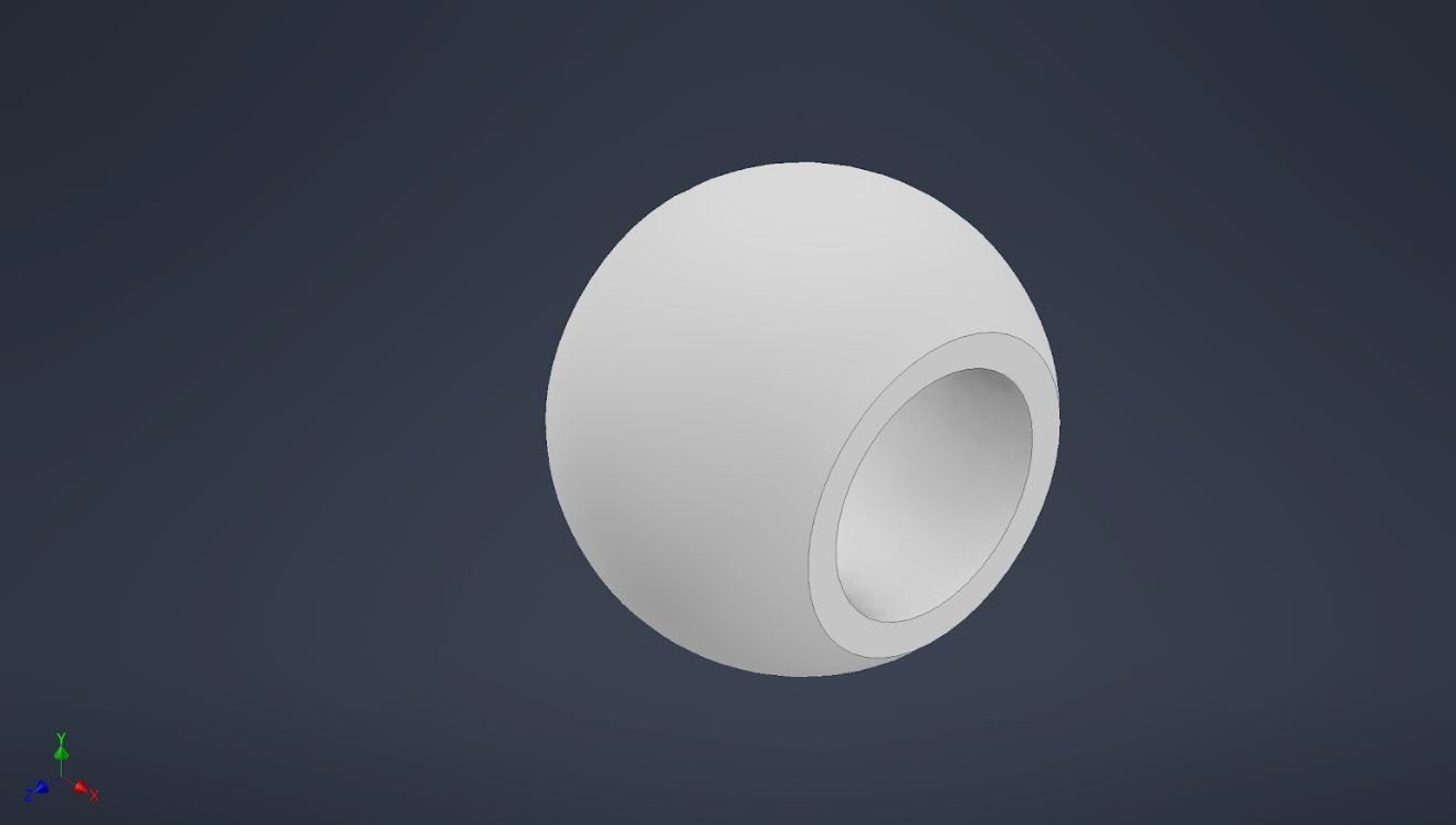
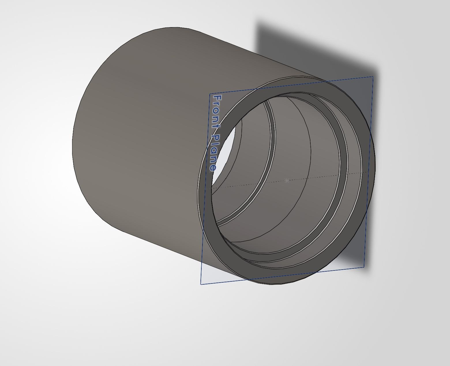
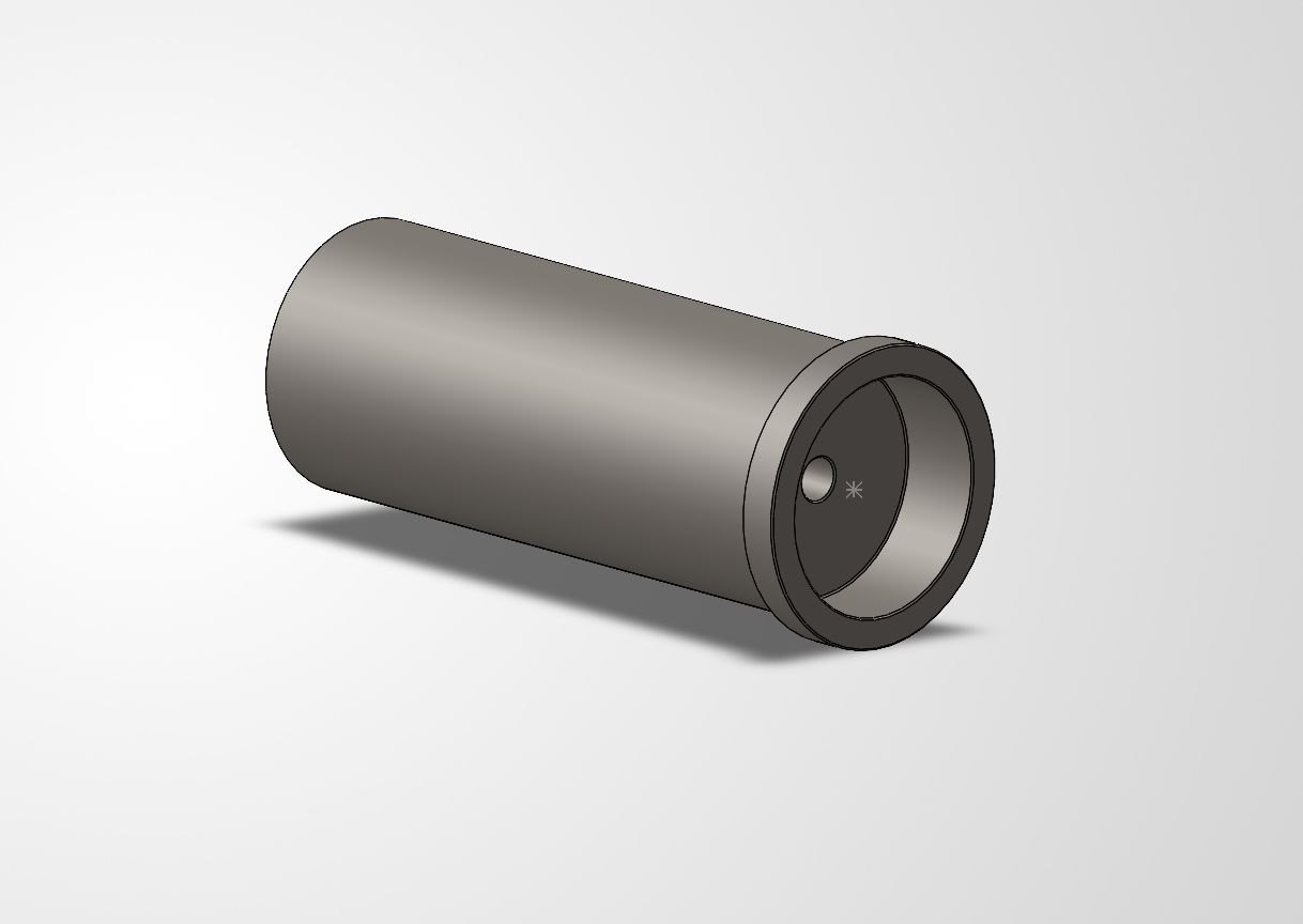
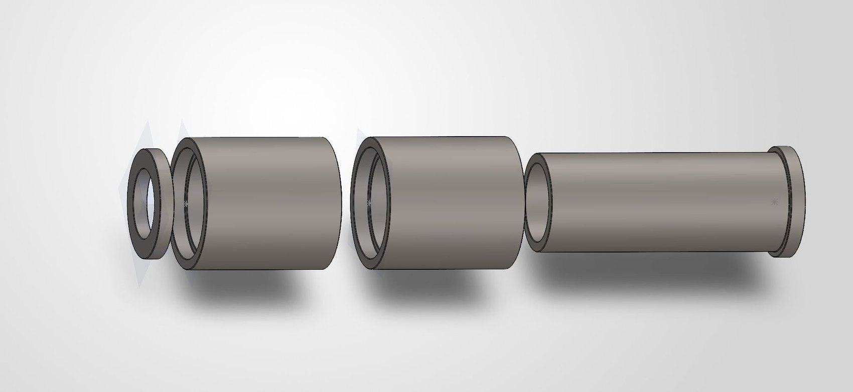
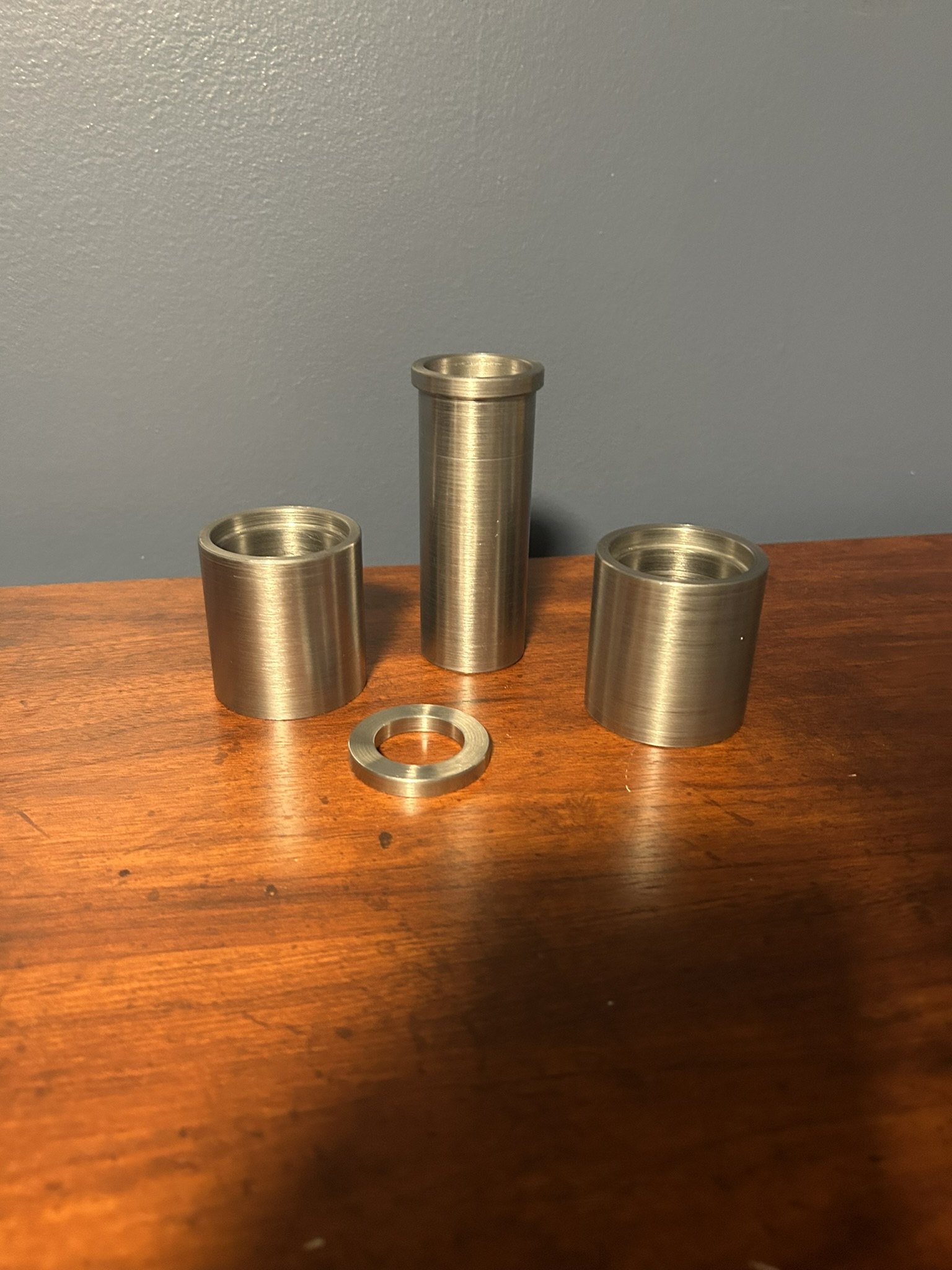
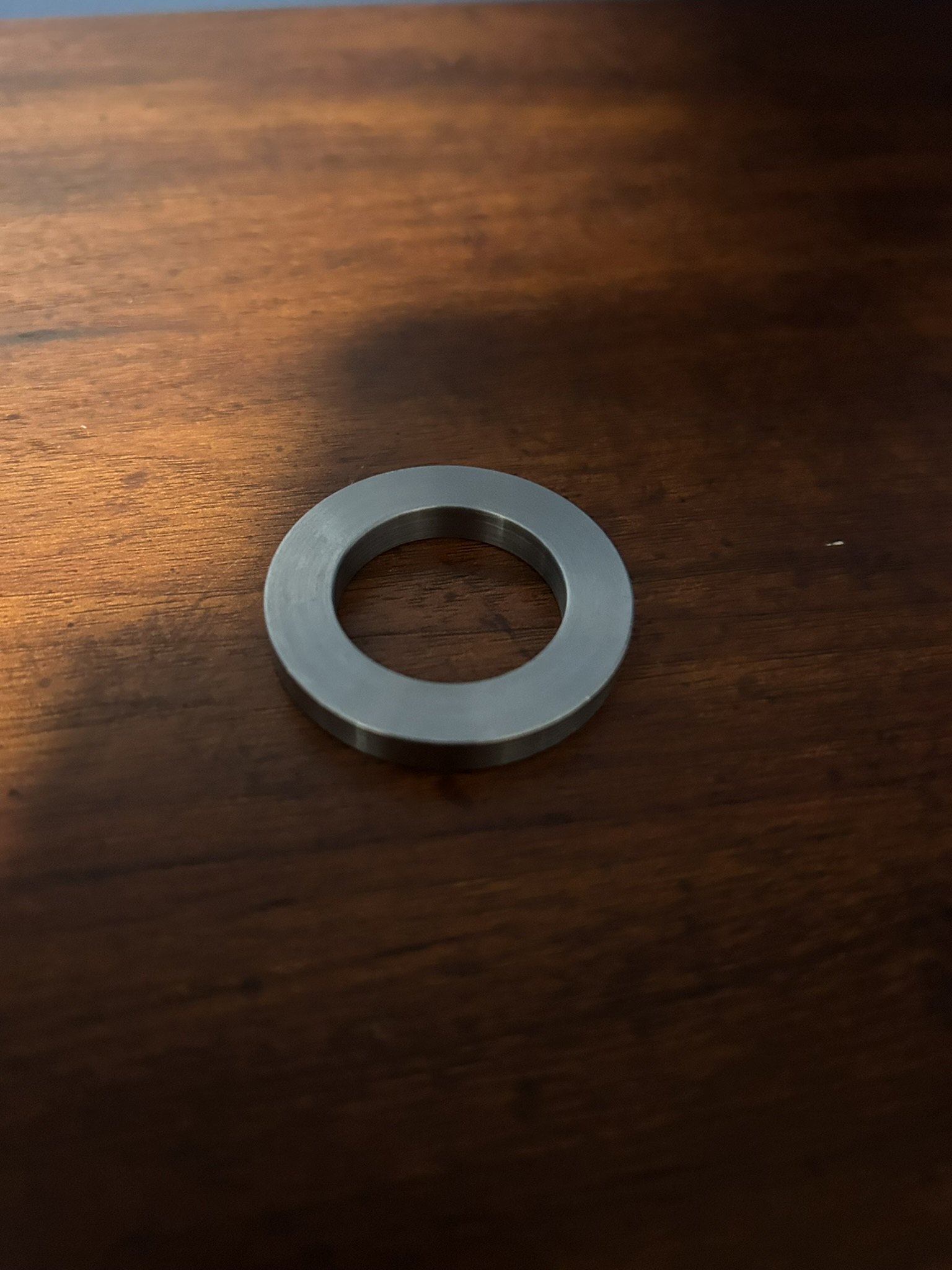
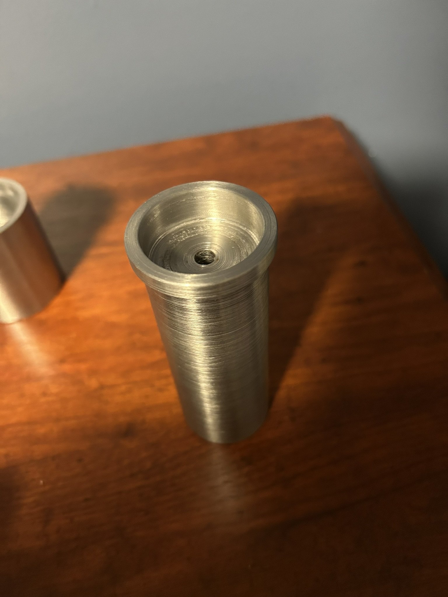
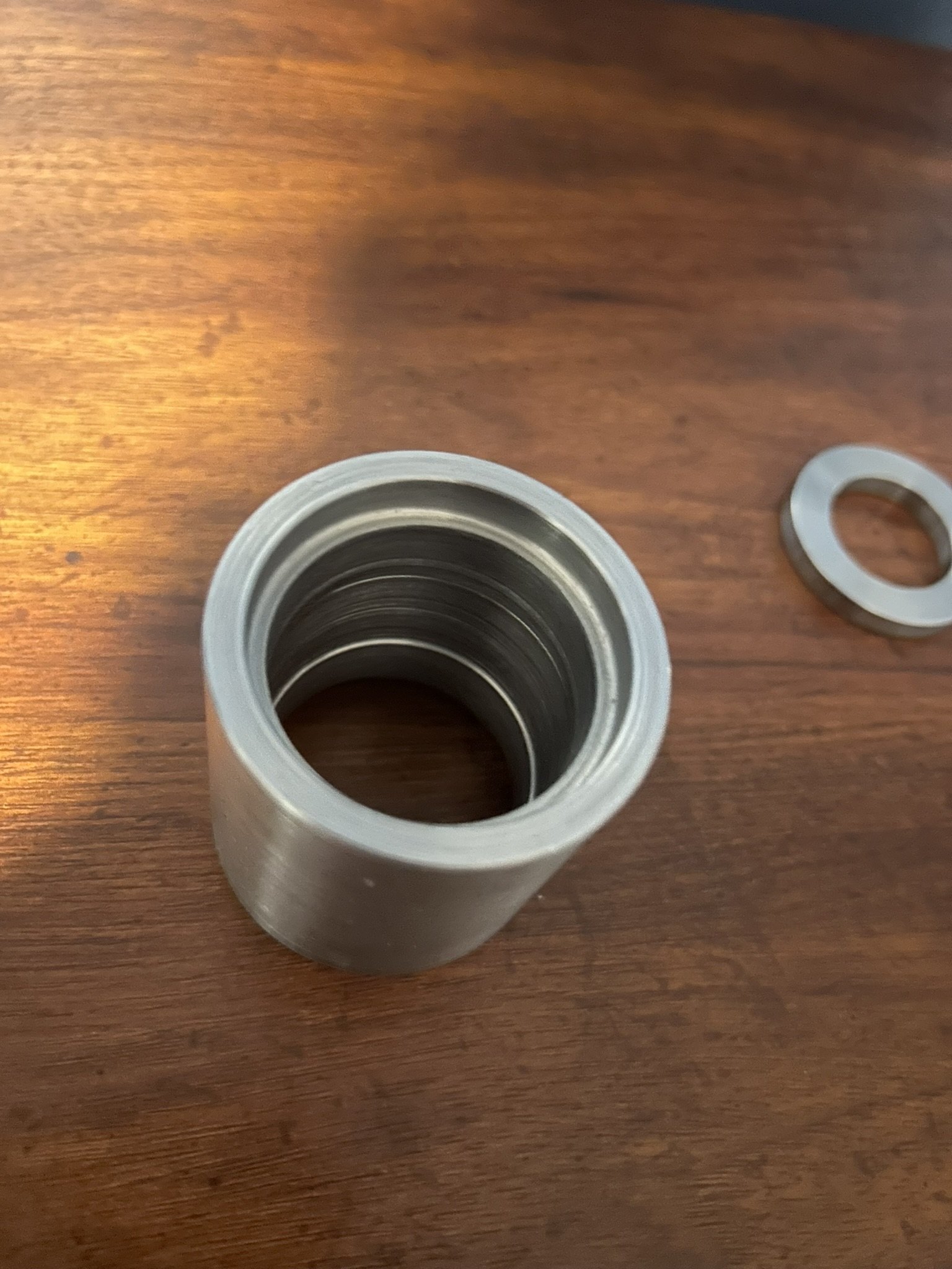
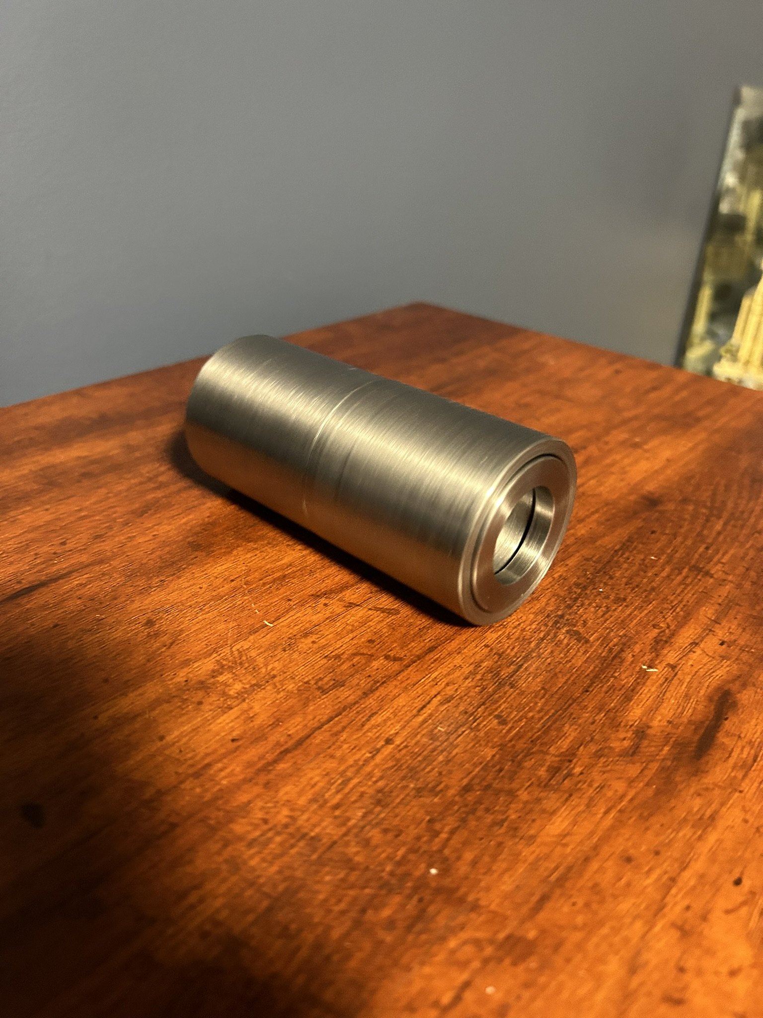
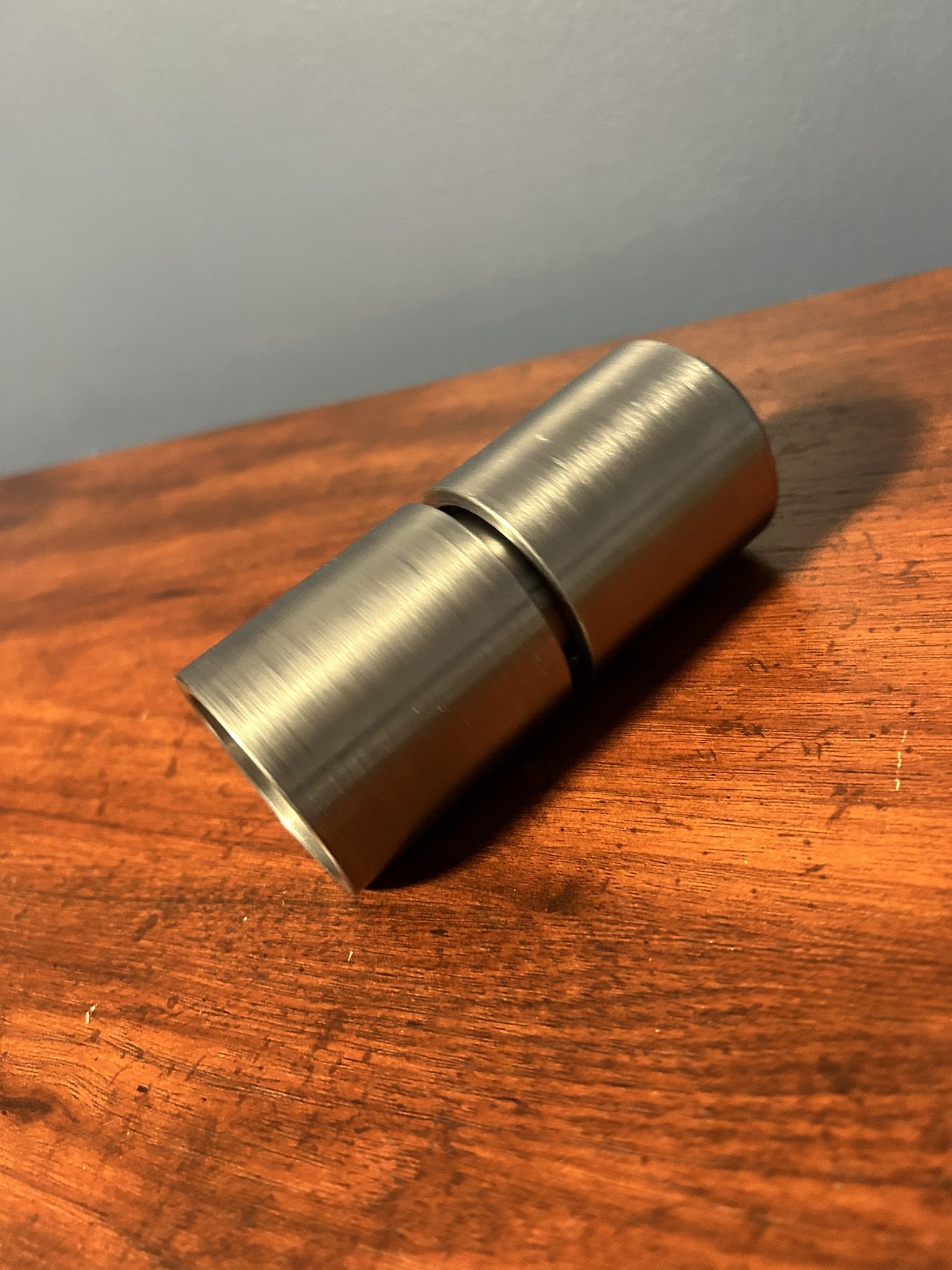
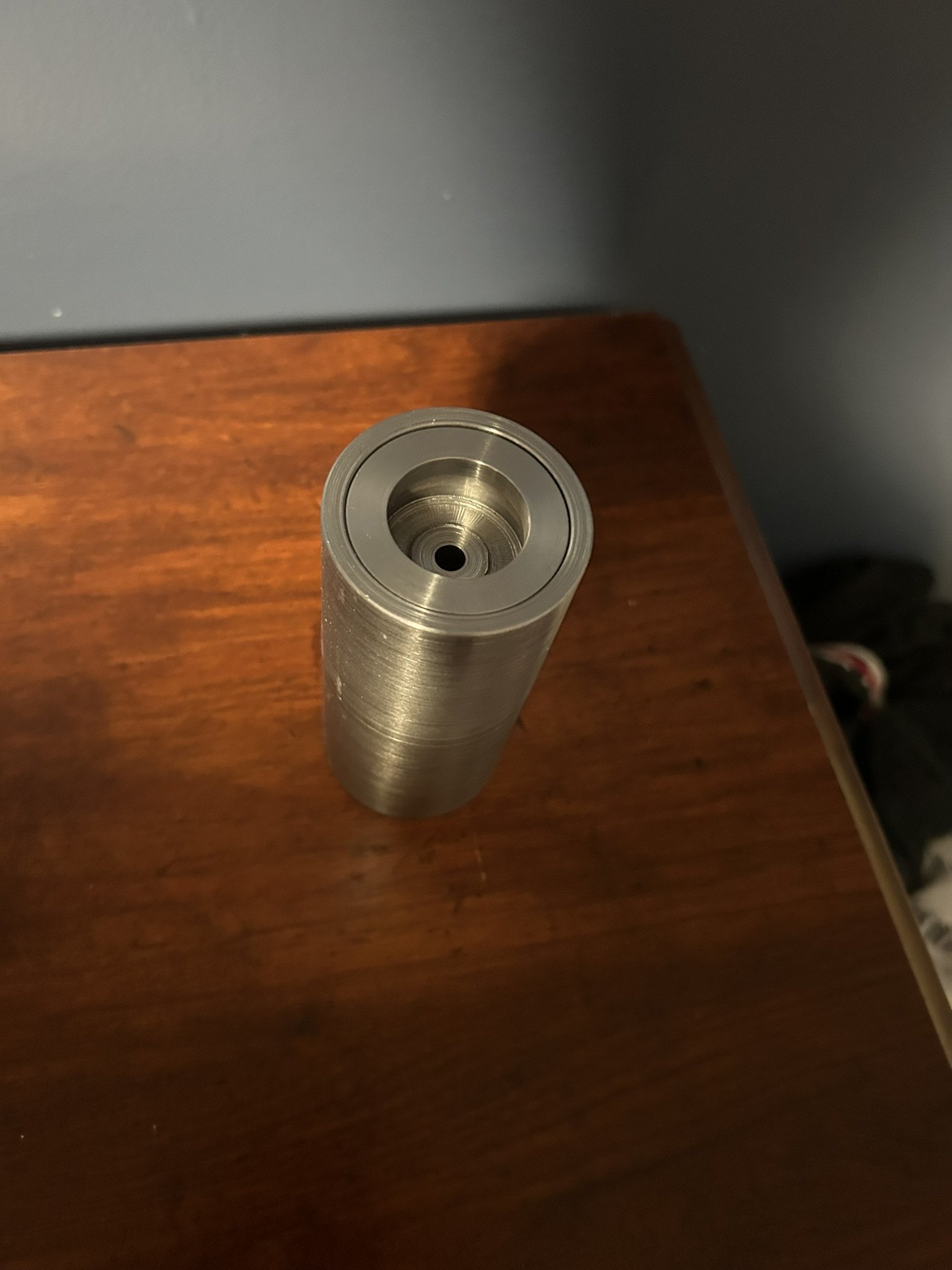
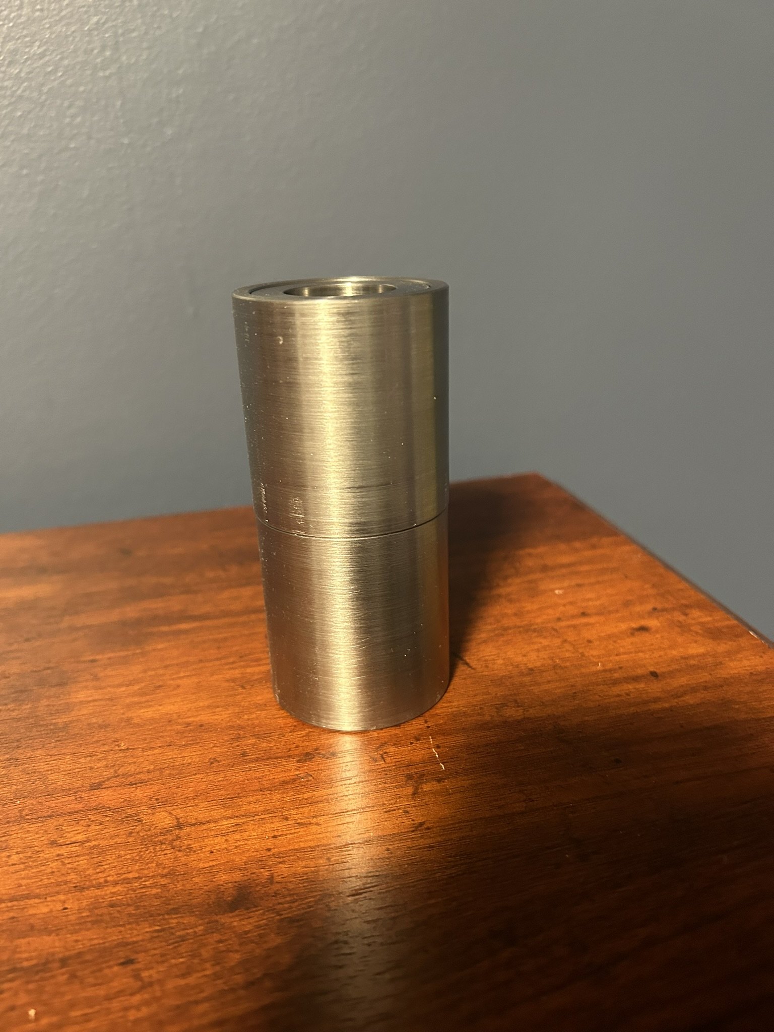
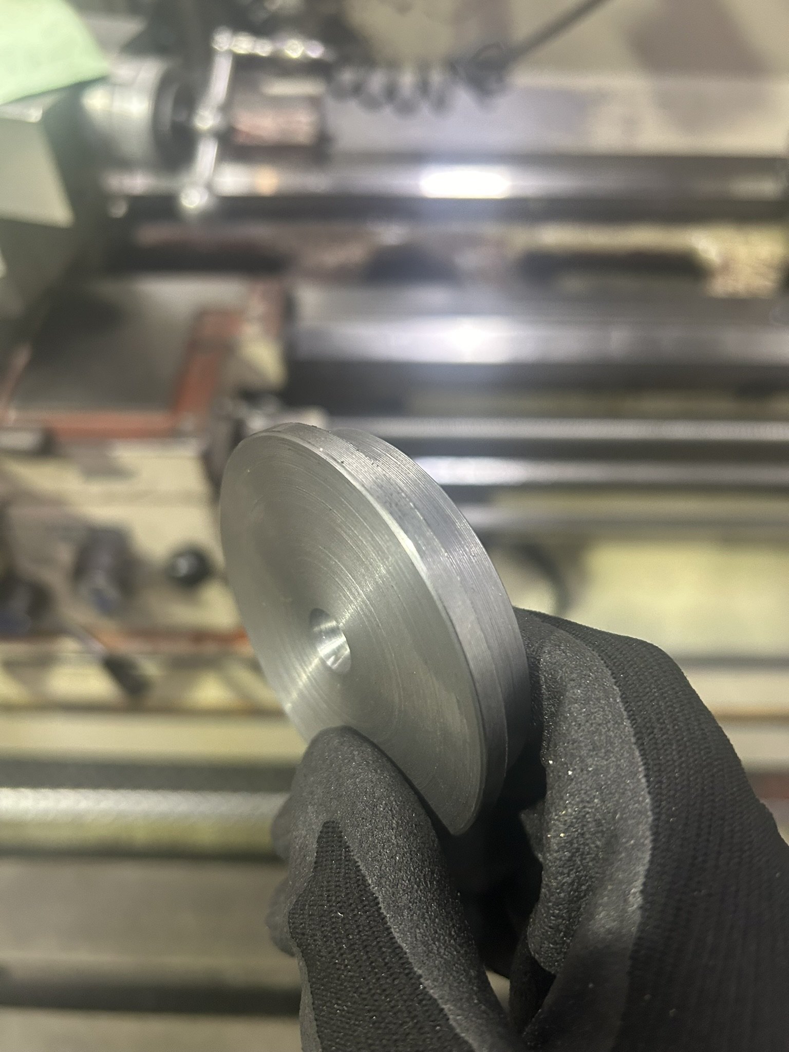
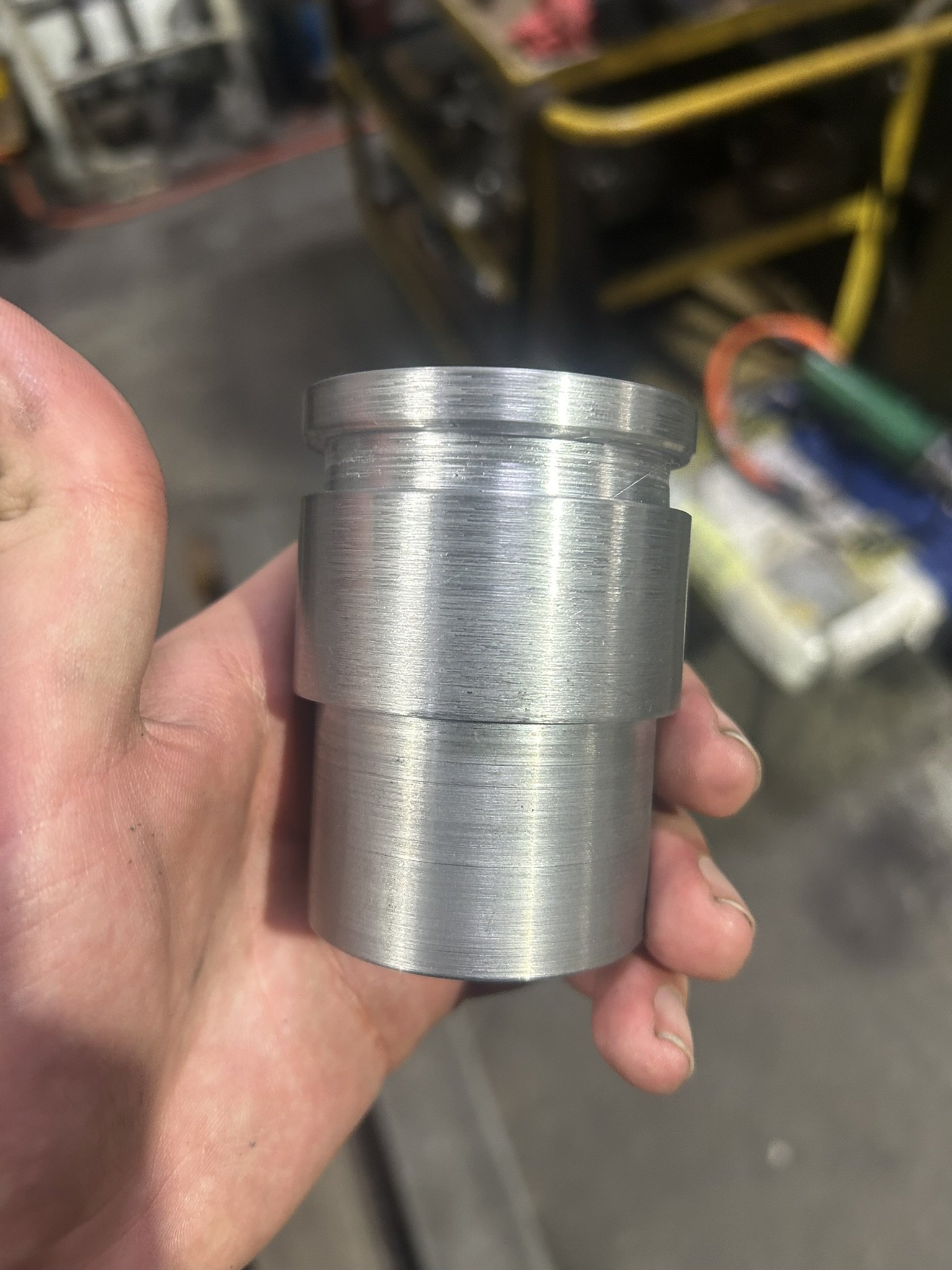
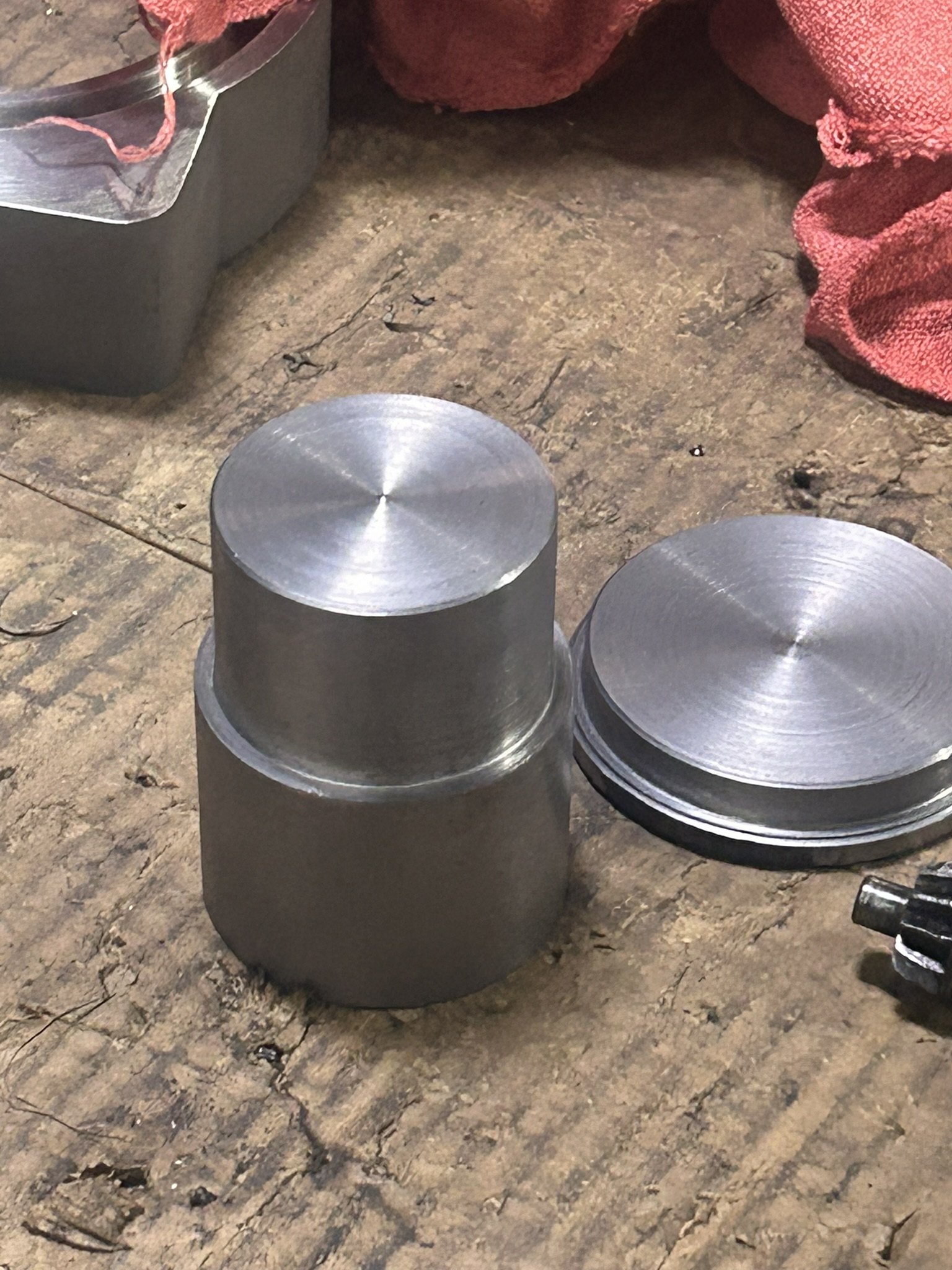
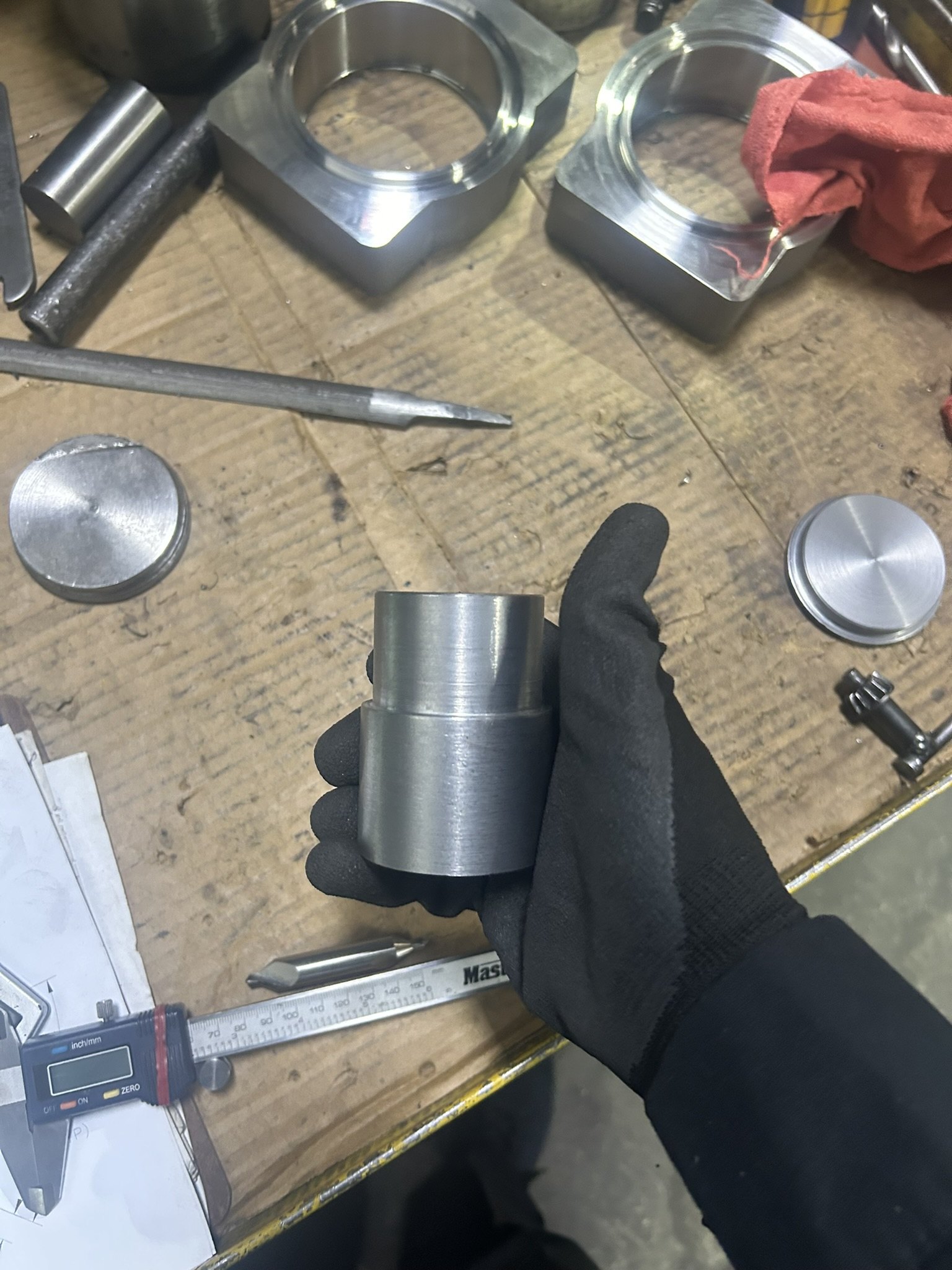
Bemco makes rolls for steel mills, and the sleeved roll is their own design. A solid roll wears out where the impact lands. So the roll gets split into a hub carrying one or two sleeves. A worn sleeve is reversed to use its unworn side, and the two sleeves can be swapped. Two sleeves with two usable sides each is four times the life of a solid roll.
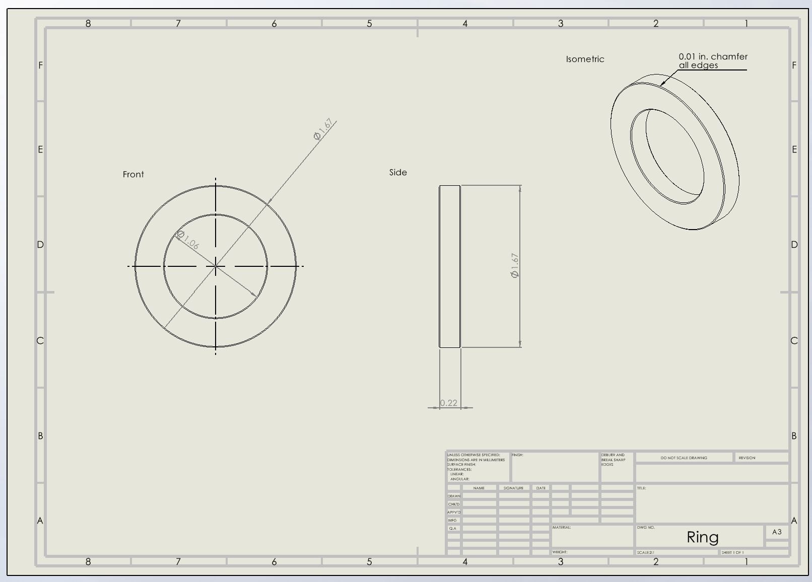
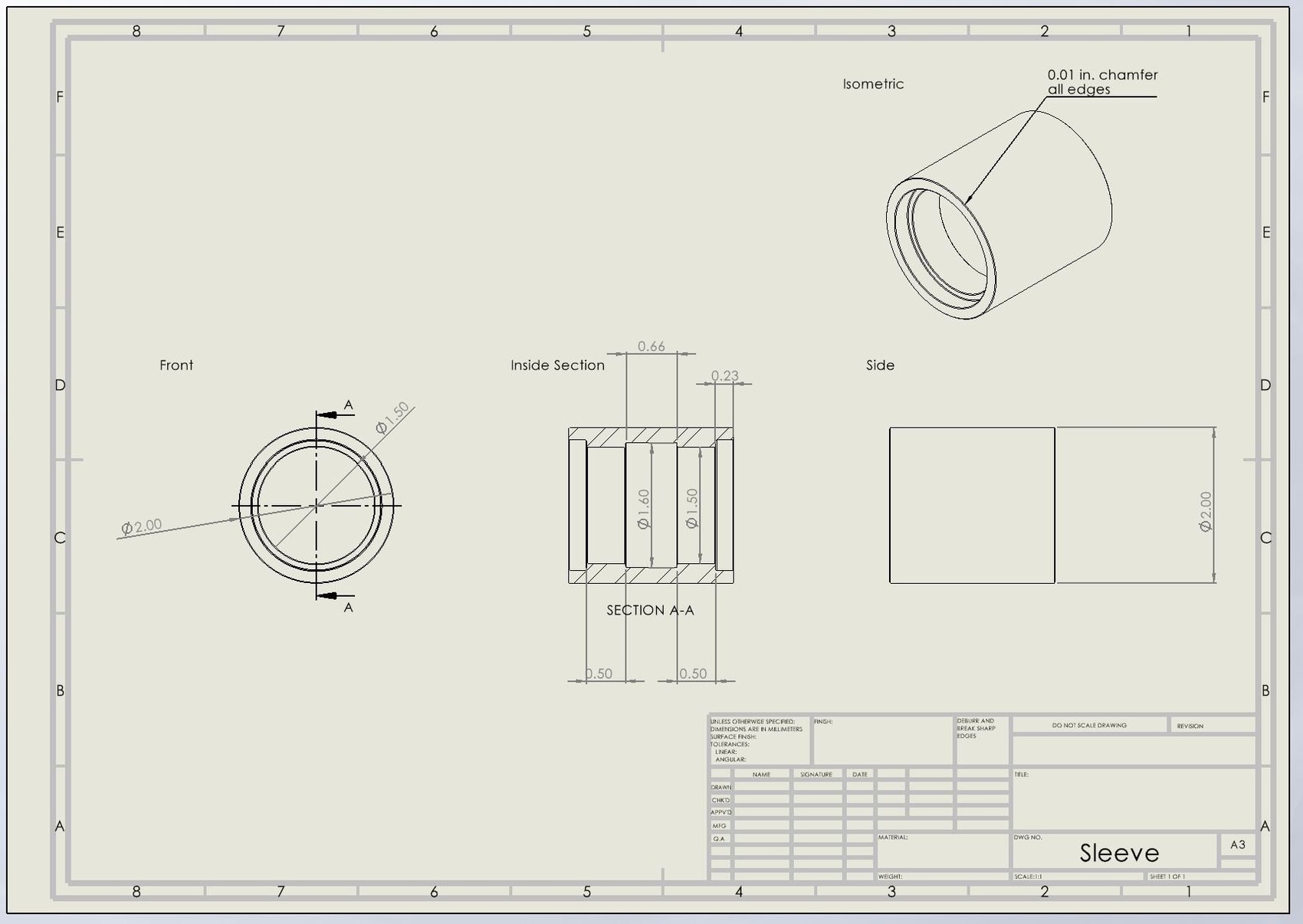
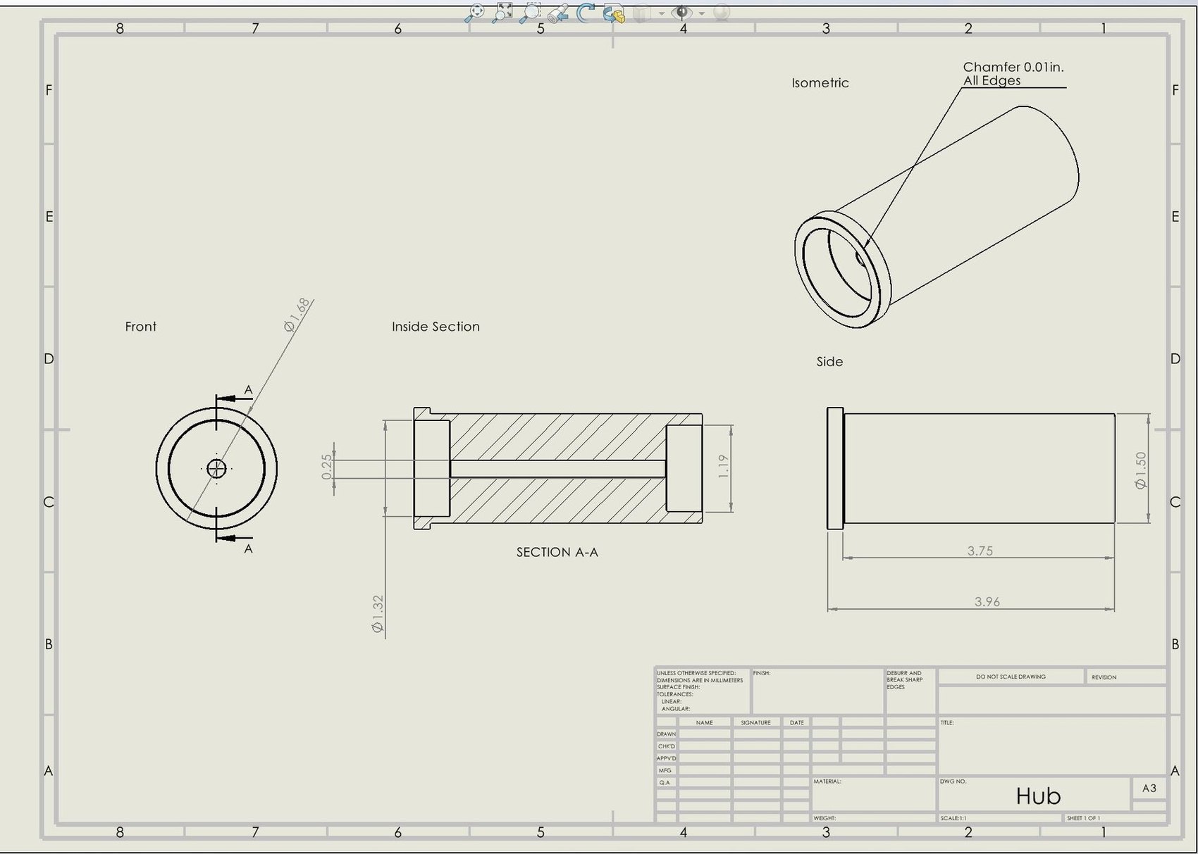
I built scaled training versions of the full two-sleeve assembly. First I modelled the hub, sleeves and ring in SolidWorks. Then I drew them with section views and chamfer callouts, machined the parts on manual and CNC lathes, and put them together to check the fit.
From Part to Drawing
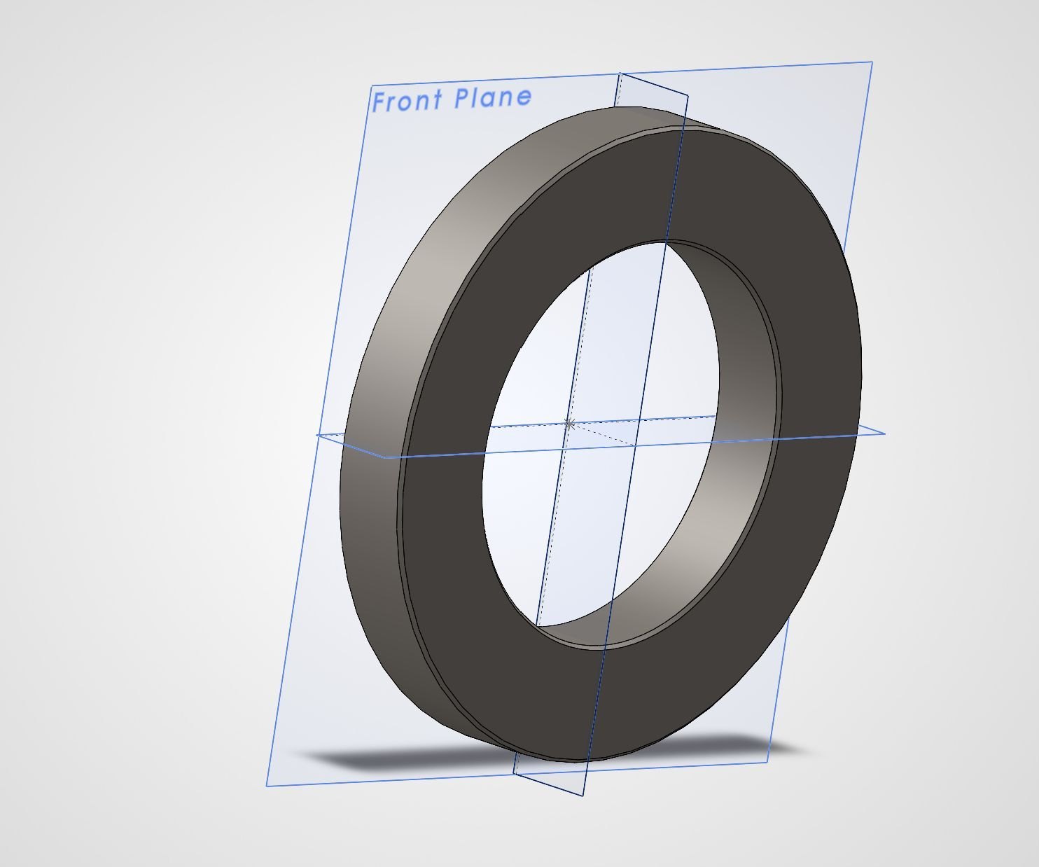
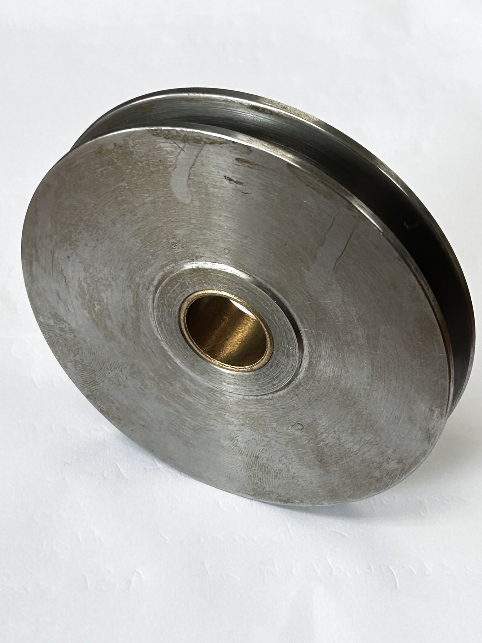
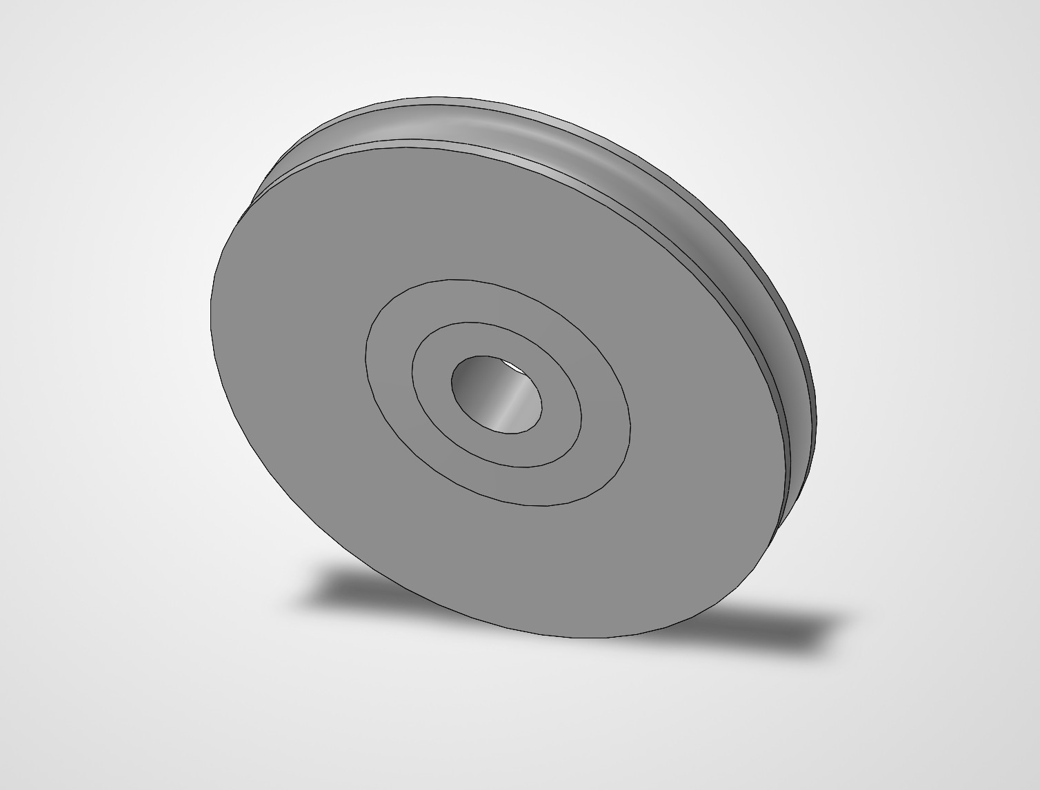
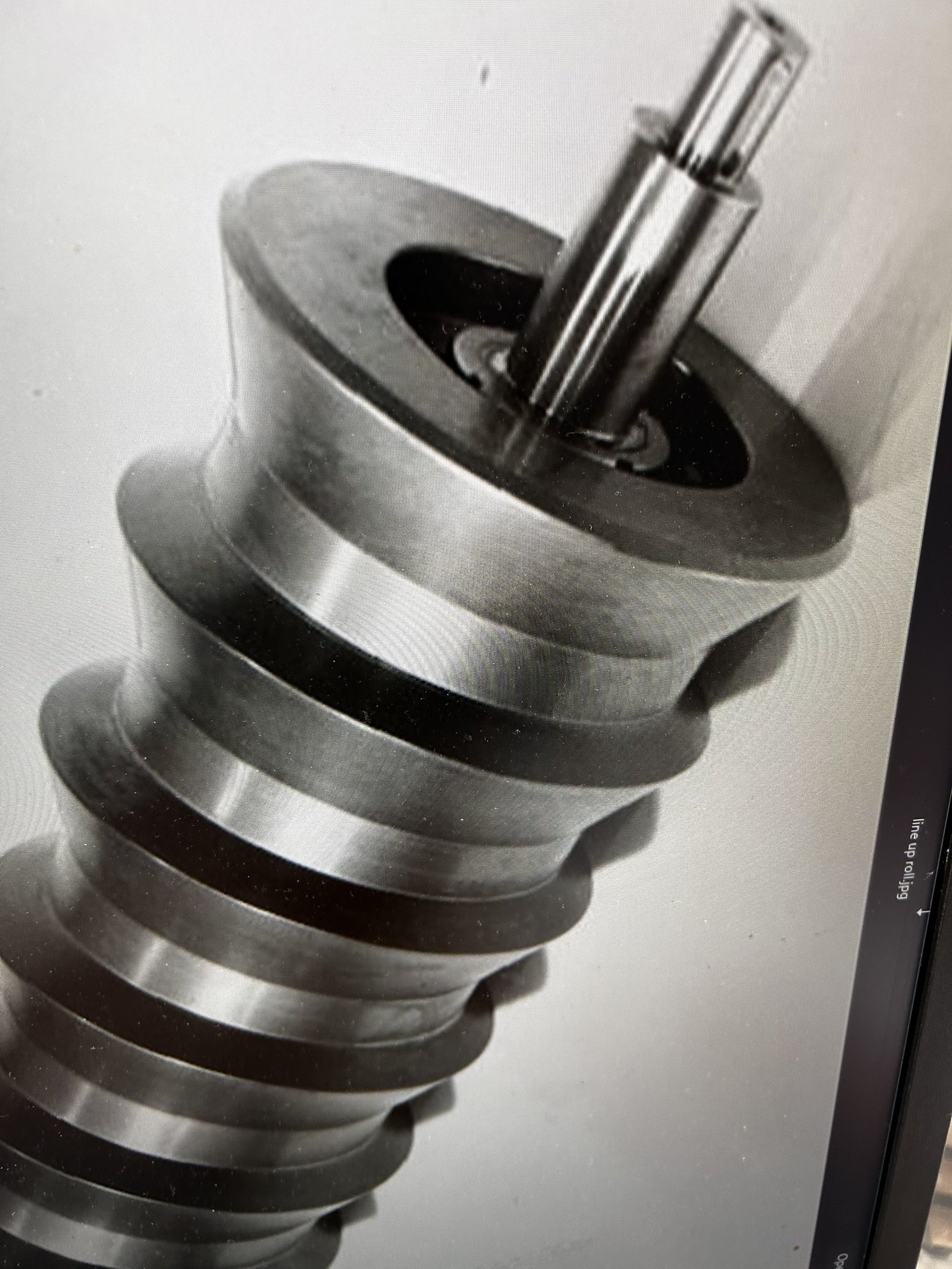
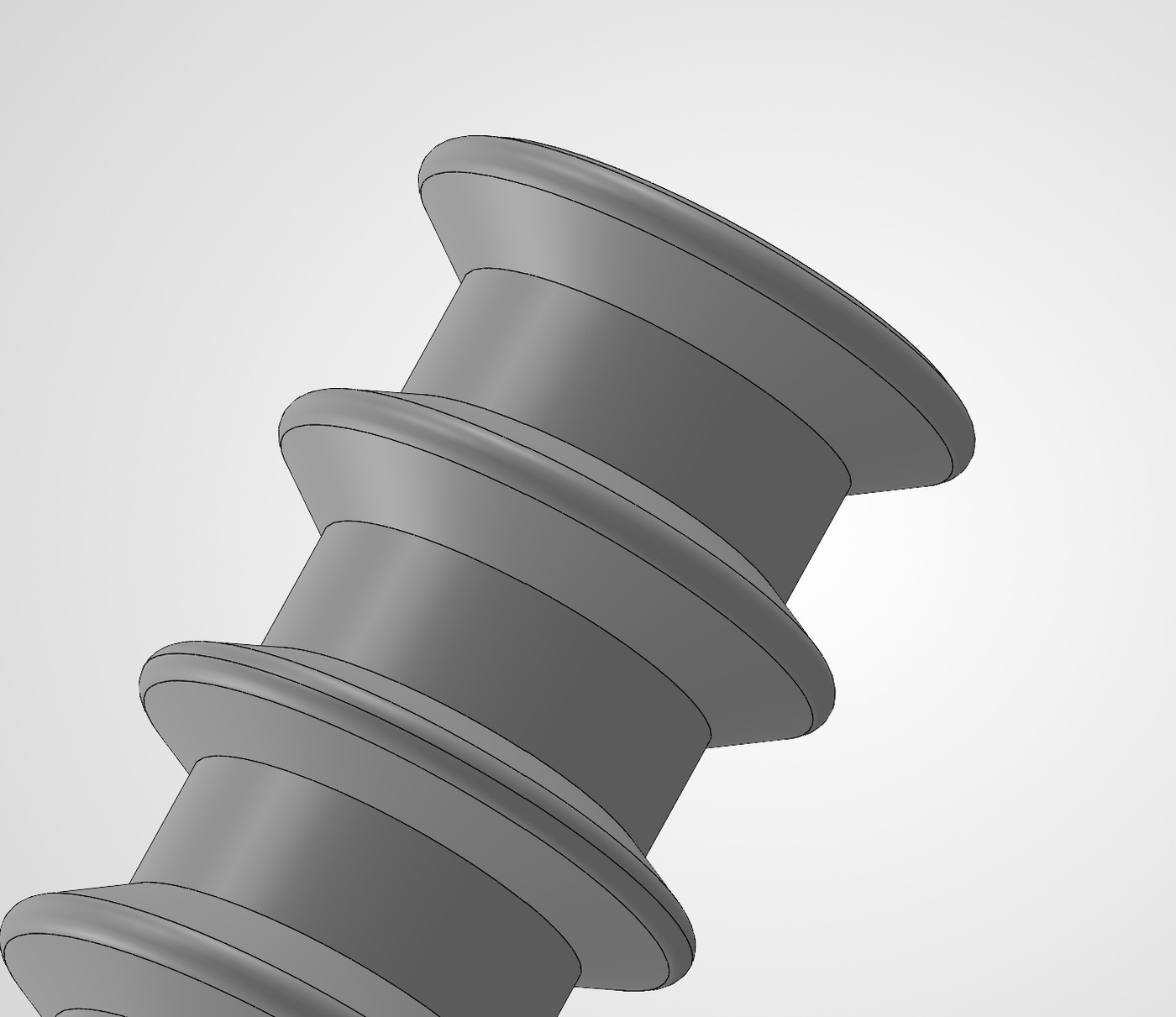
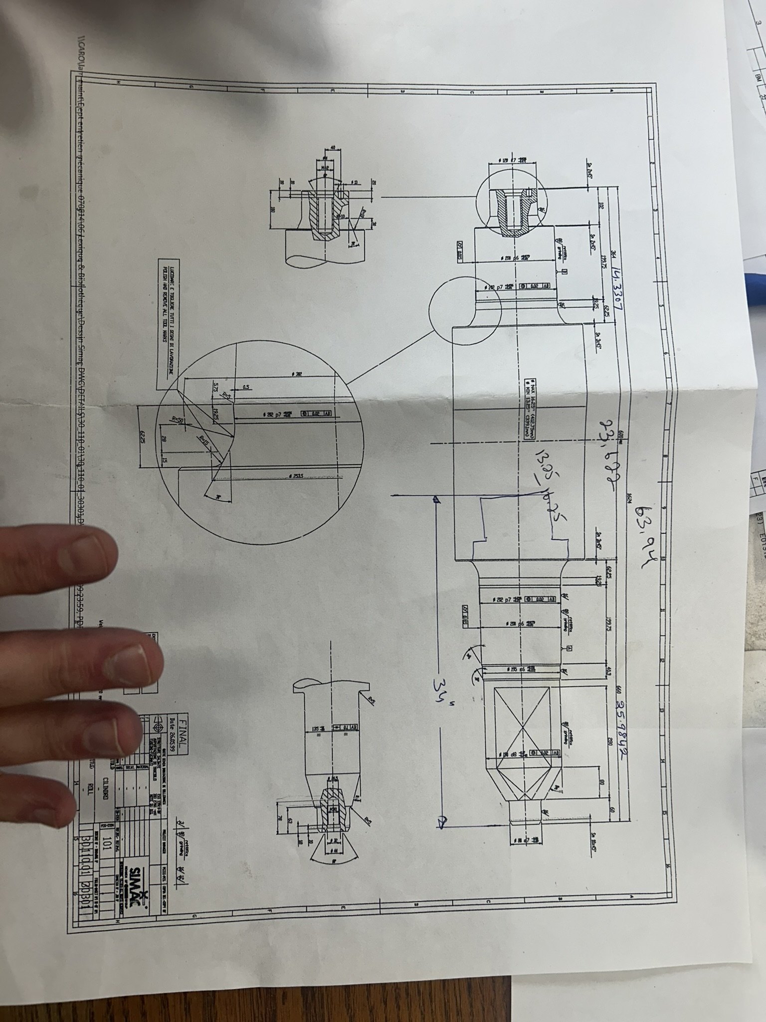
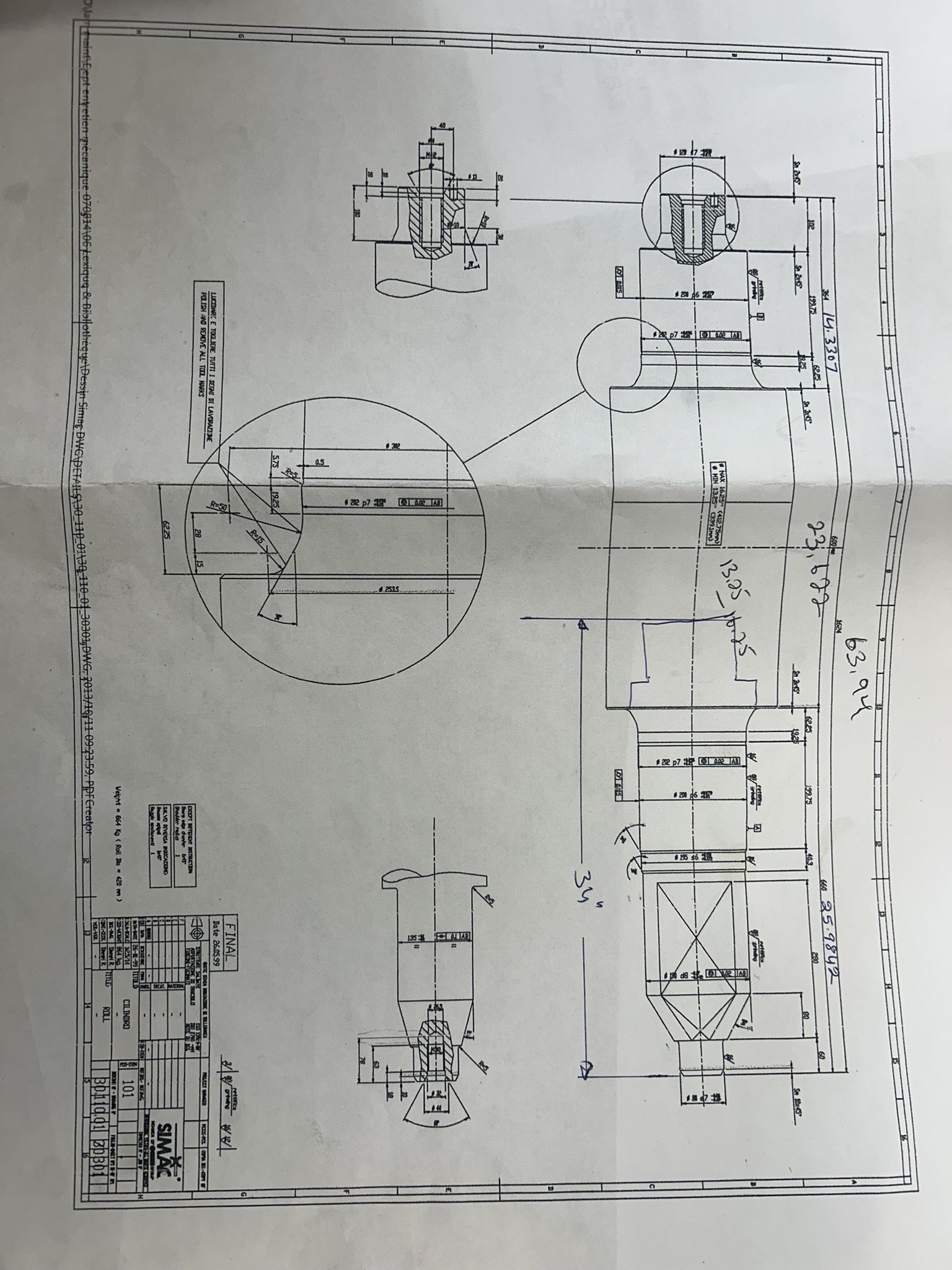
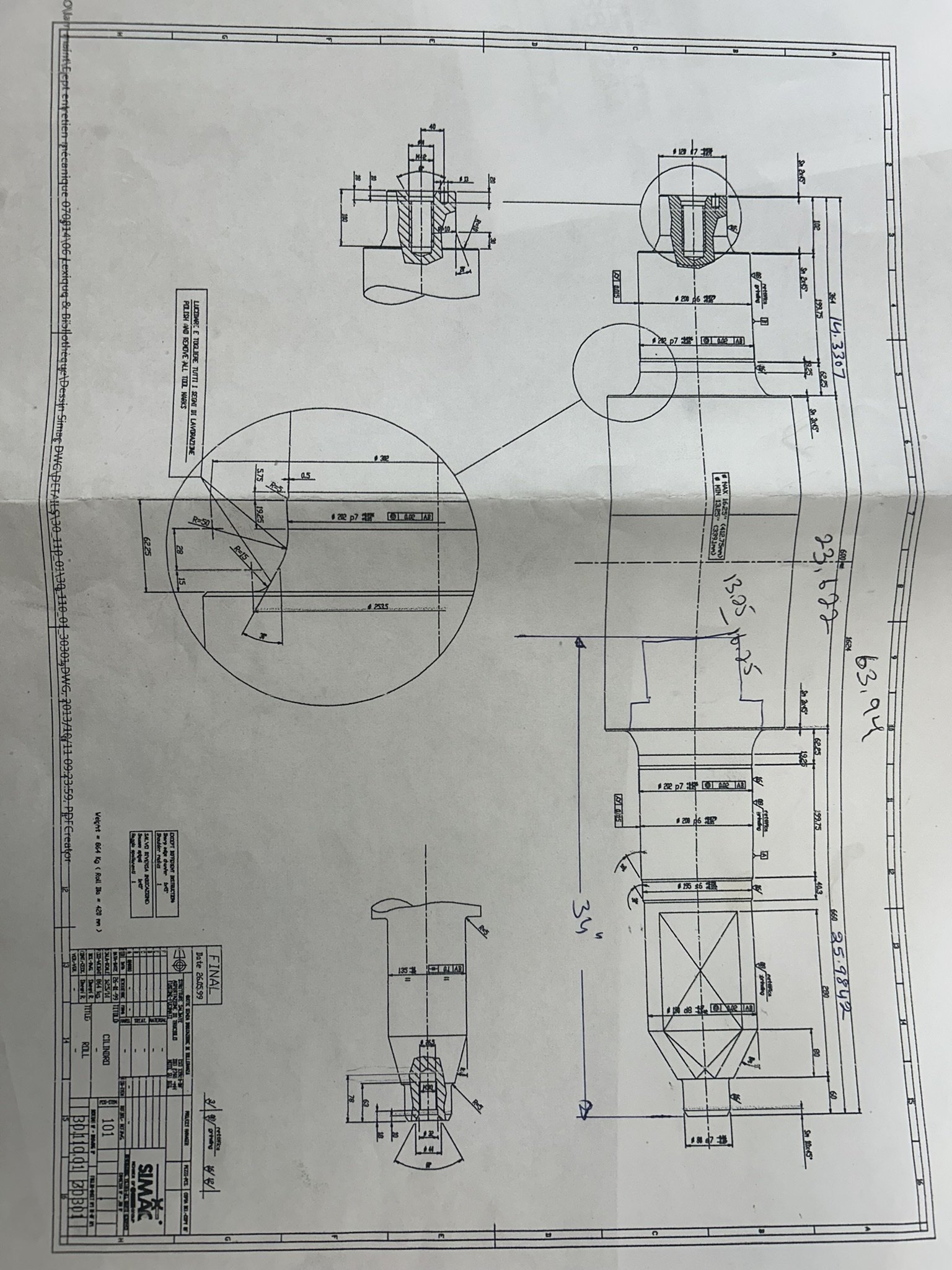
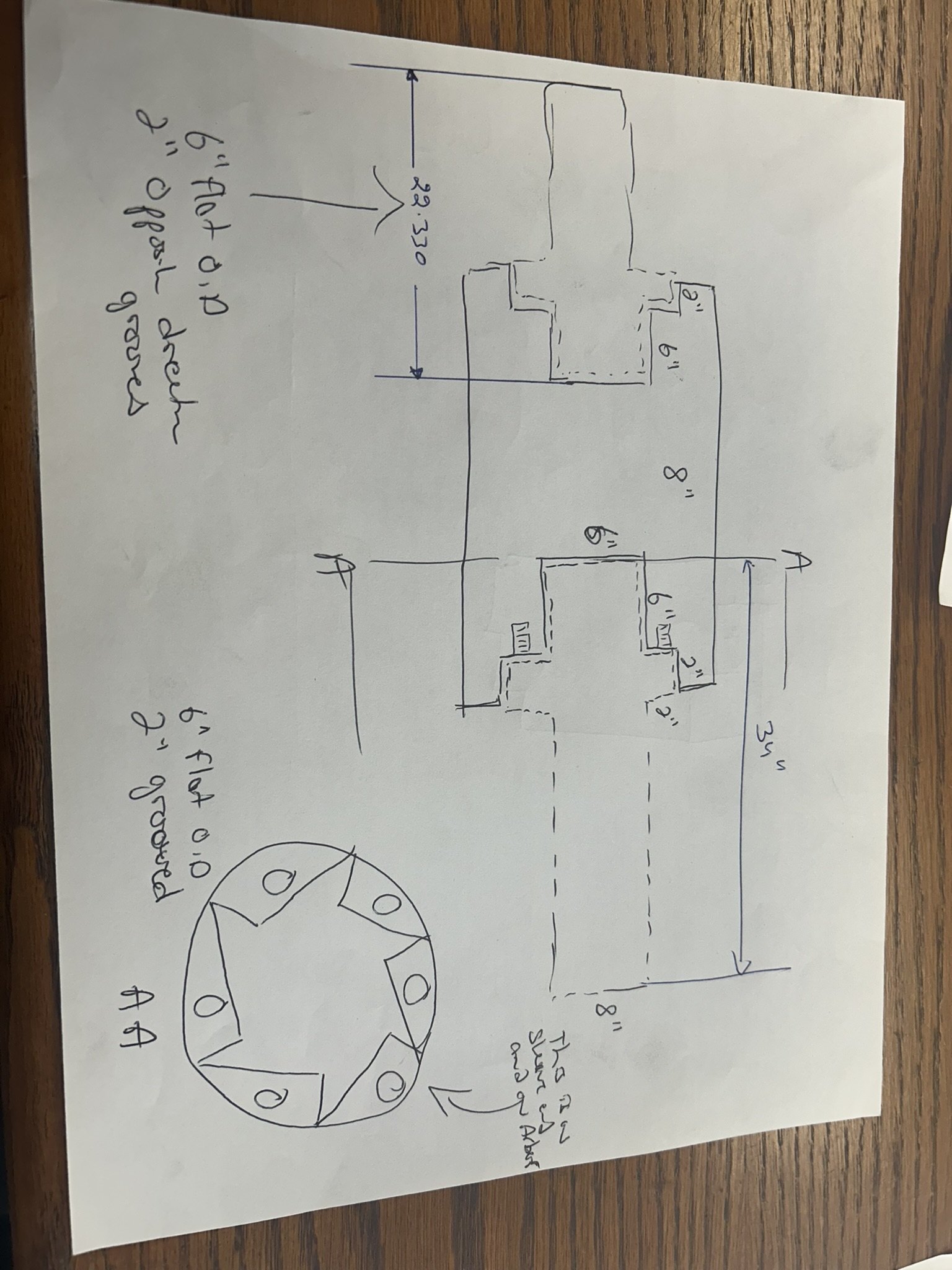
A lot of the parts we made had no drawings. They were legacy components, and the only record of the geometry was the part itself. So I measured them and rebuilt them in SolidWorks, geometry, tolerances and GD&T callouts. Those drawings went to the floor and parts were machined from them. That is the part I would point to. If I got a dimension wrong, somebody was going to cut it wrong.
Machining from Drawings
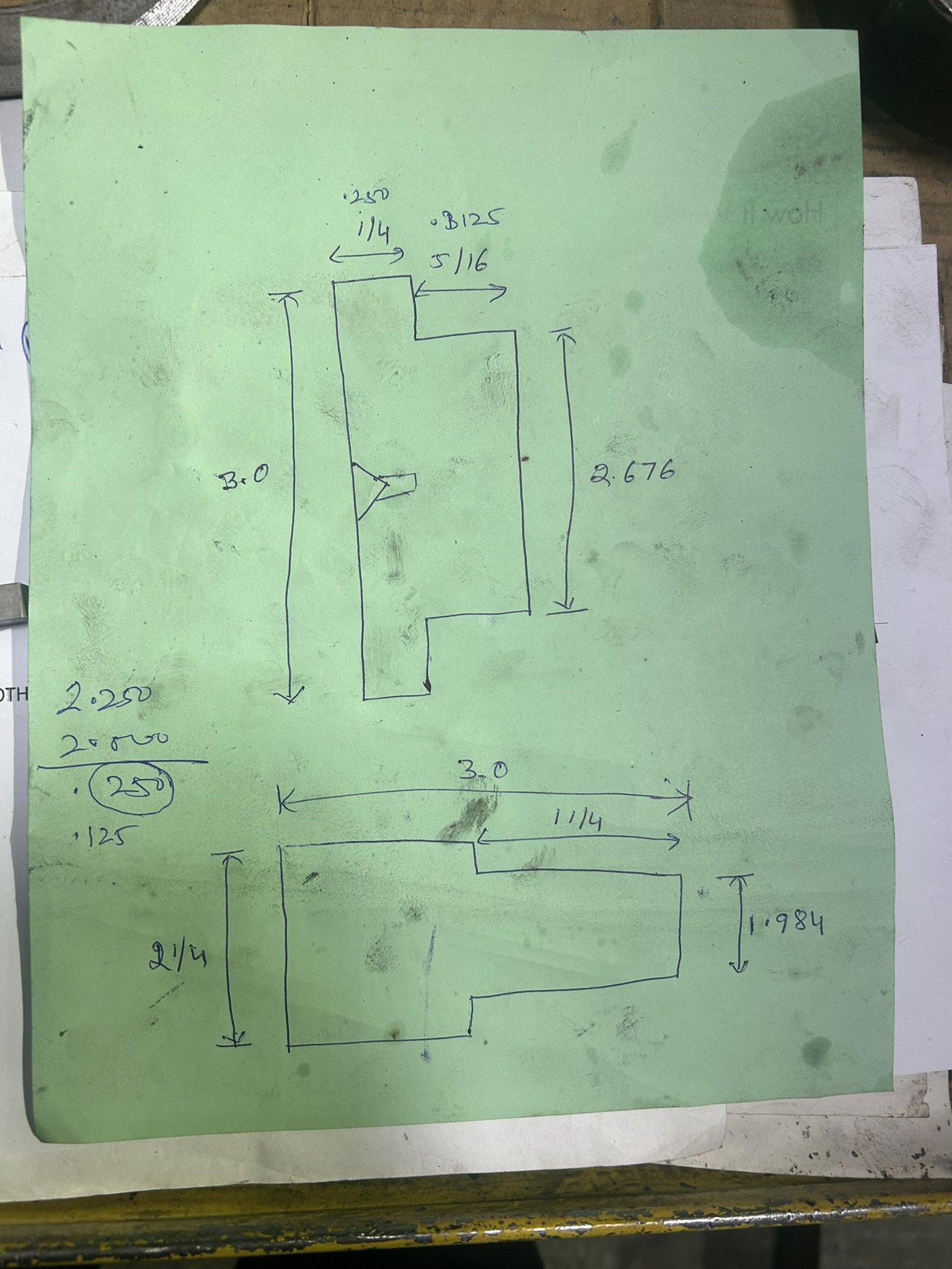
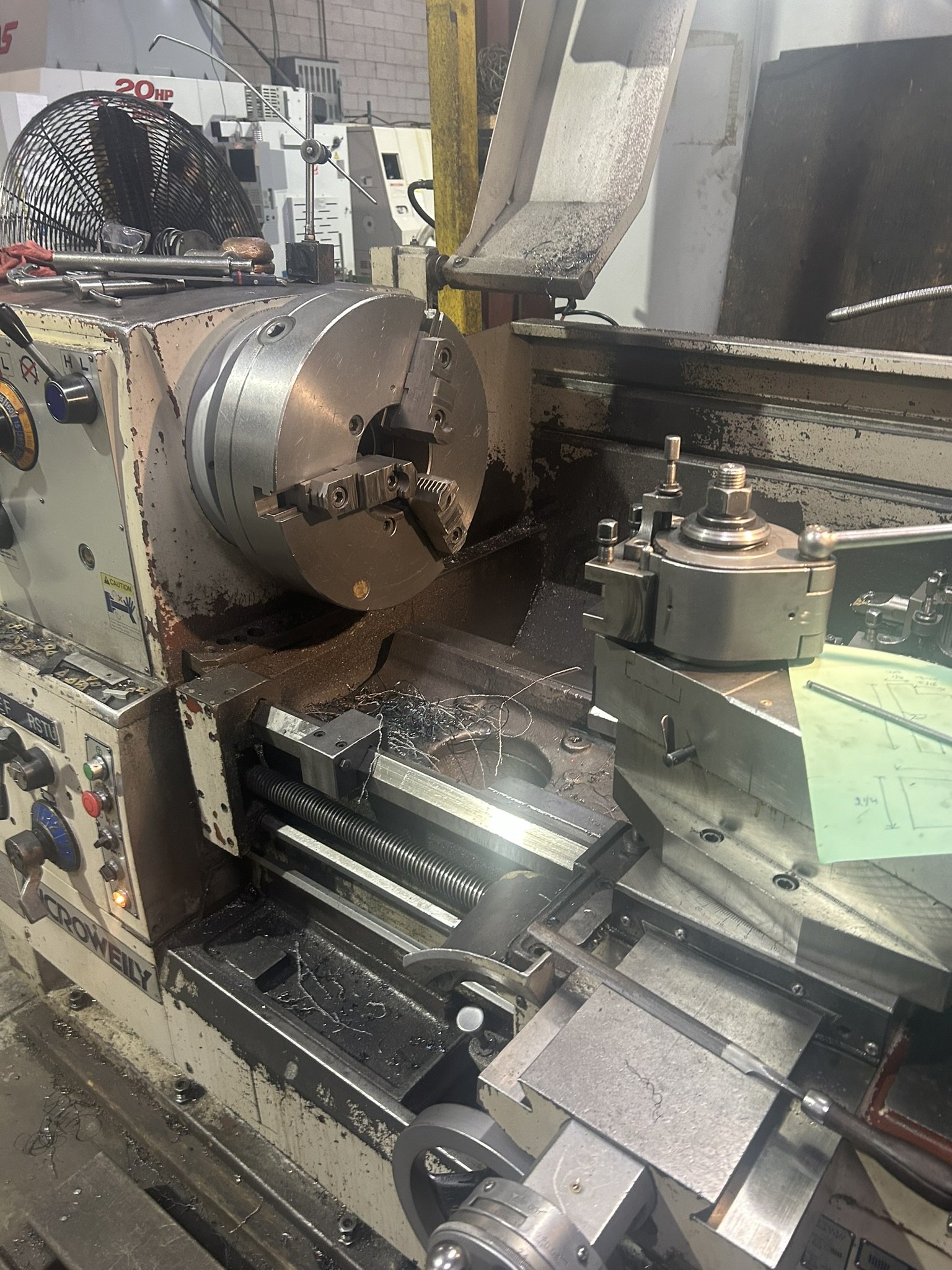
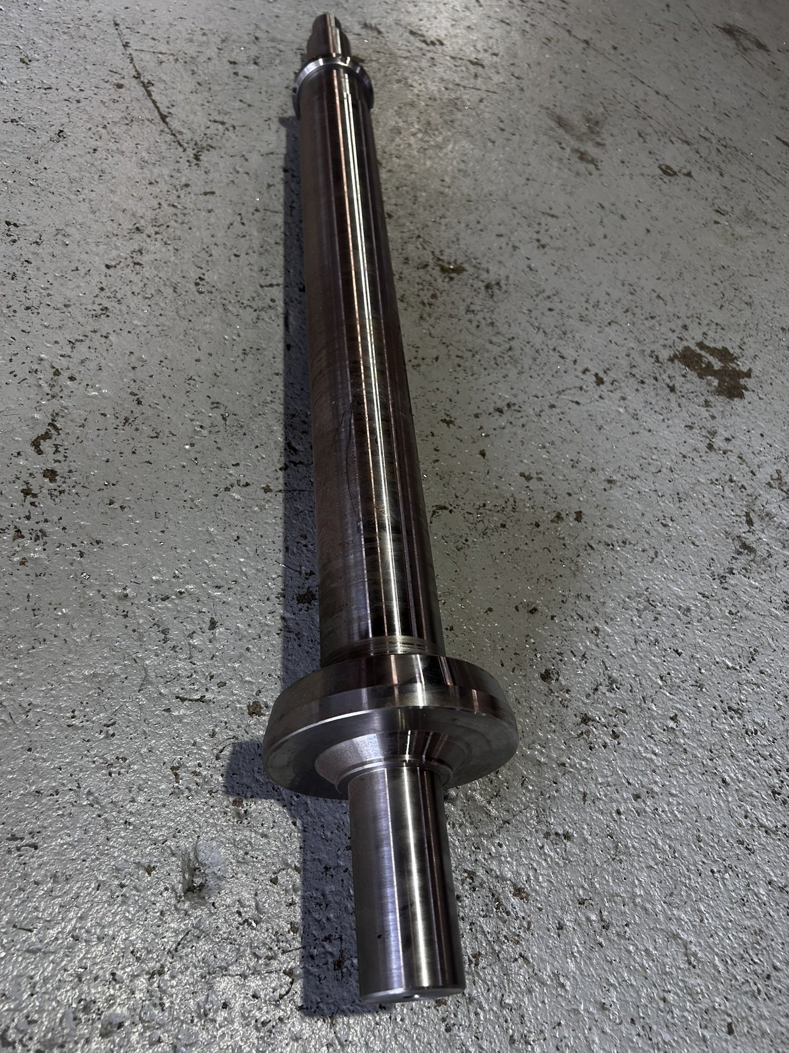
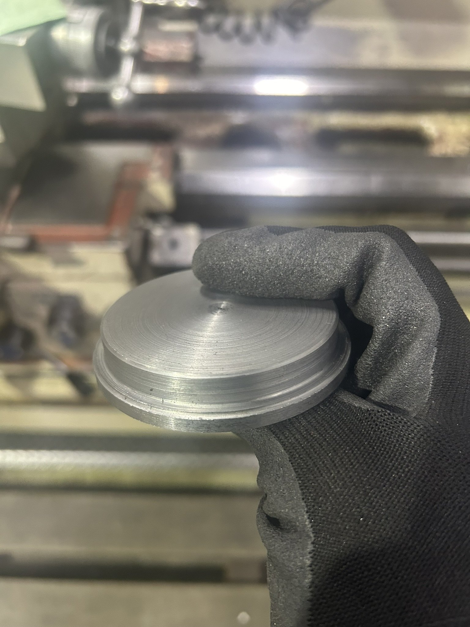
By the second summer I was running manual lathes on my own across the full job. That means reading the drawing, planning the operation sequence, choosing tooling and speeds and feeds, and inspecting in process to hold the tolerance. Nobody was setting it up for me.
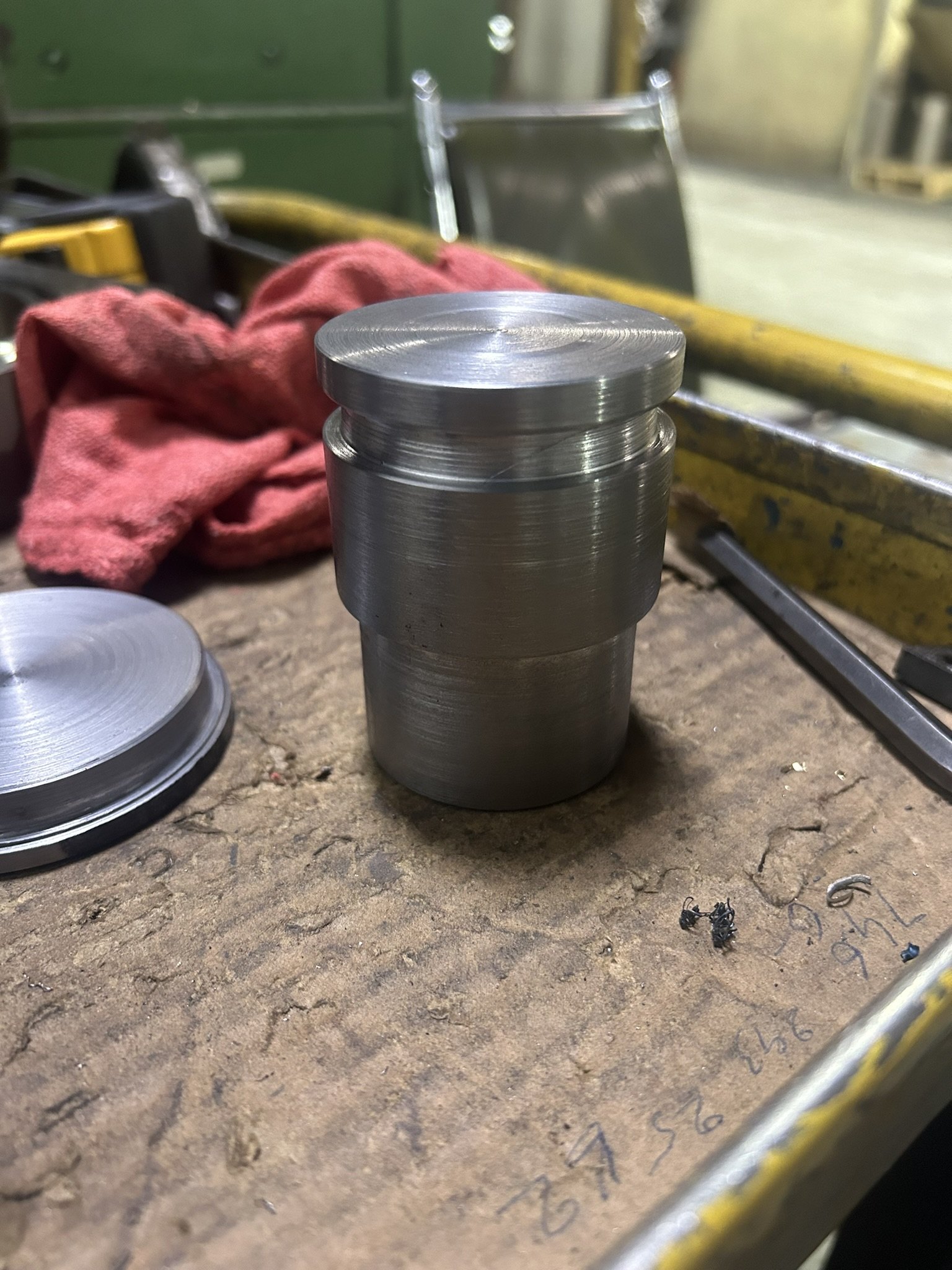
Production Quality Control System
Bemco machines rolls and roll components to tight drawing tolerances. However, the problem I kept noticing wasn't on any machine. Every inspection was recorded on paper, and a measurement only got checked if someone remembered to check it. So I built the system that replaced it. Six machinists use it daily on shop-floor tablets.

The office opens a work order with the customer, drawing number, casting count, and the dimensions and tolerances for every operation. On the floor, each casting is screened proceed or not proceed before any machining time goes into it. Operators then log their actual measurements against each dimension, and every reading is checked against the tolerance as it is typed.
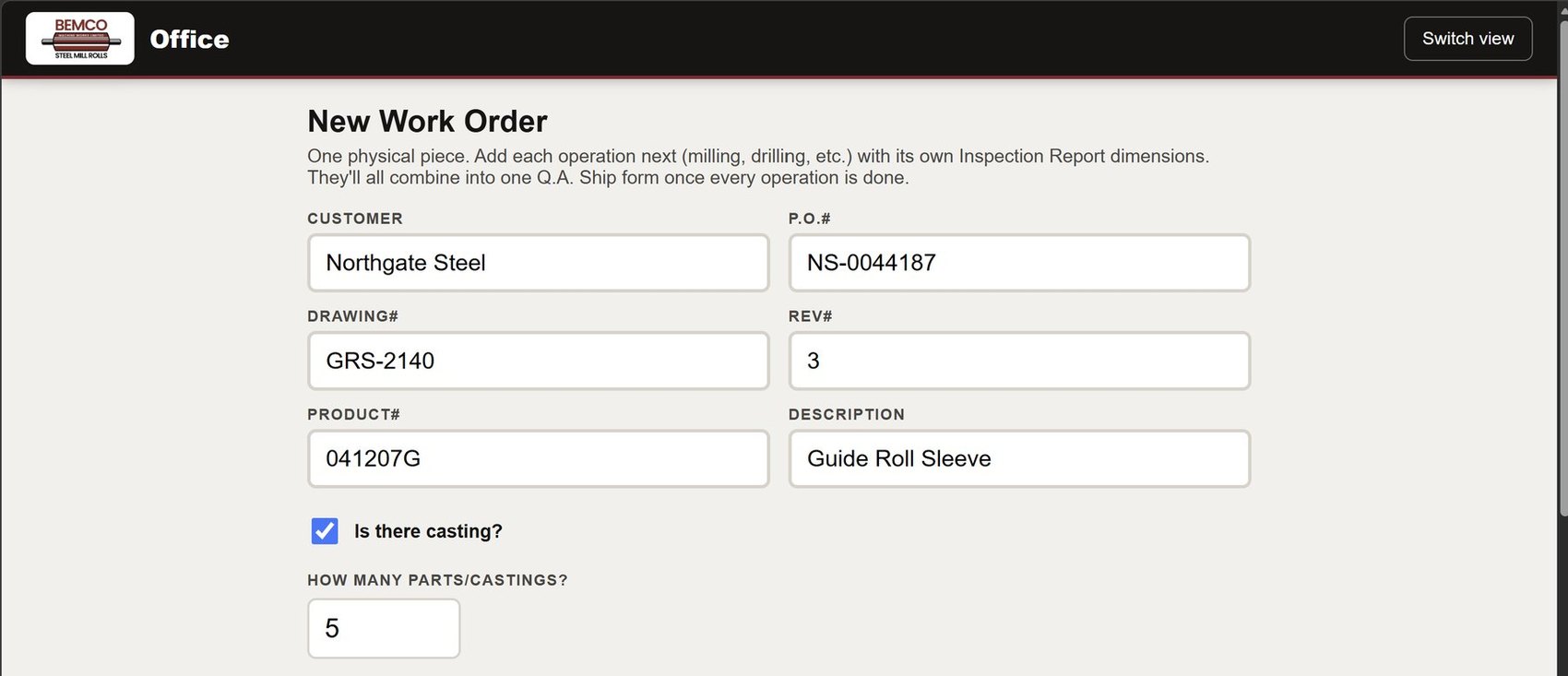
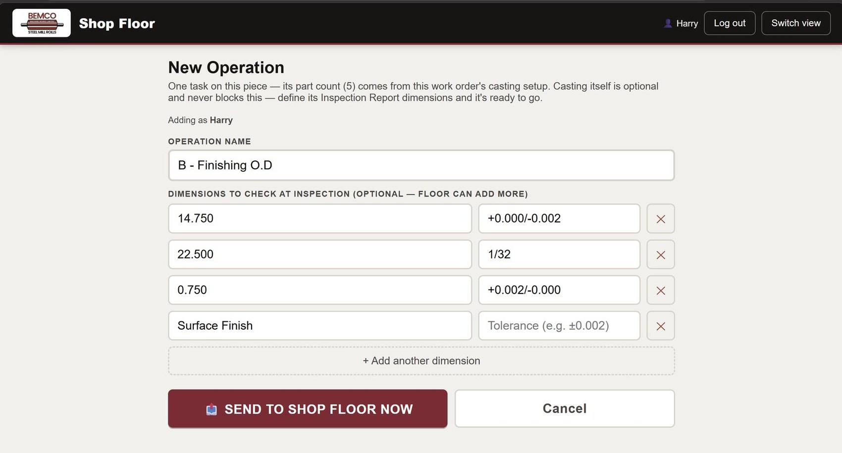
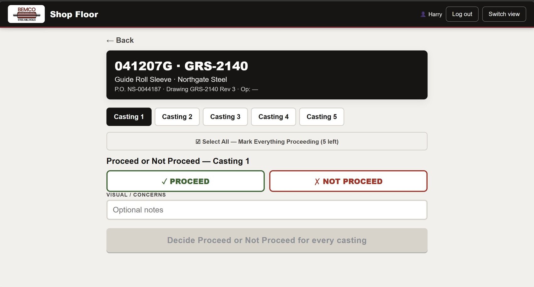
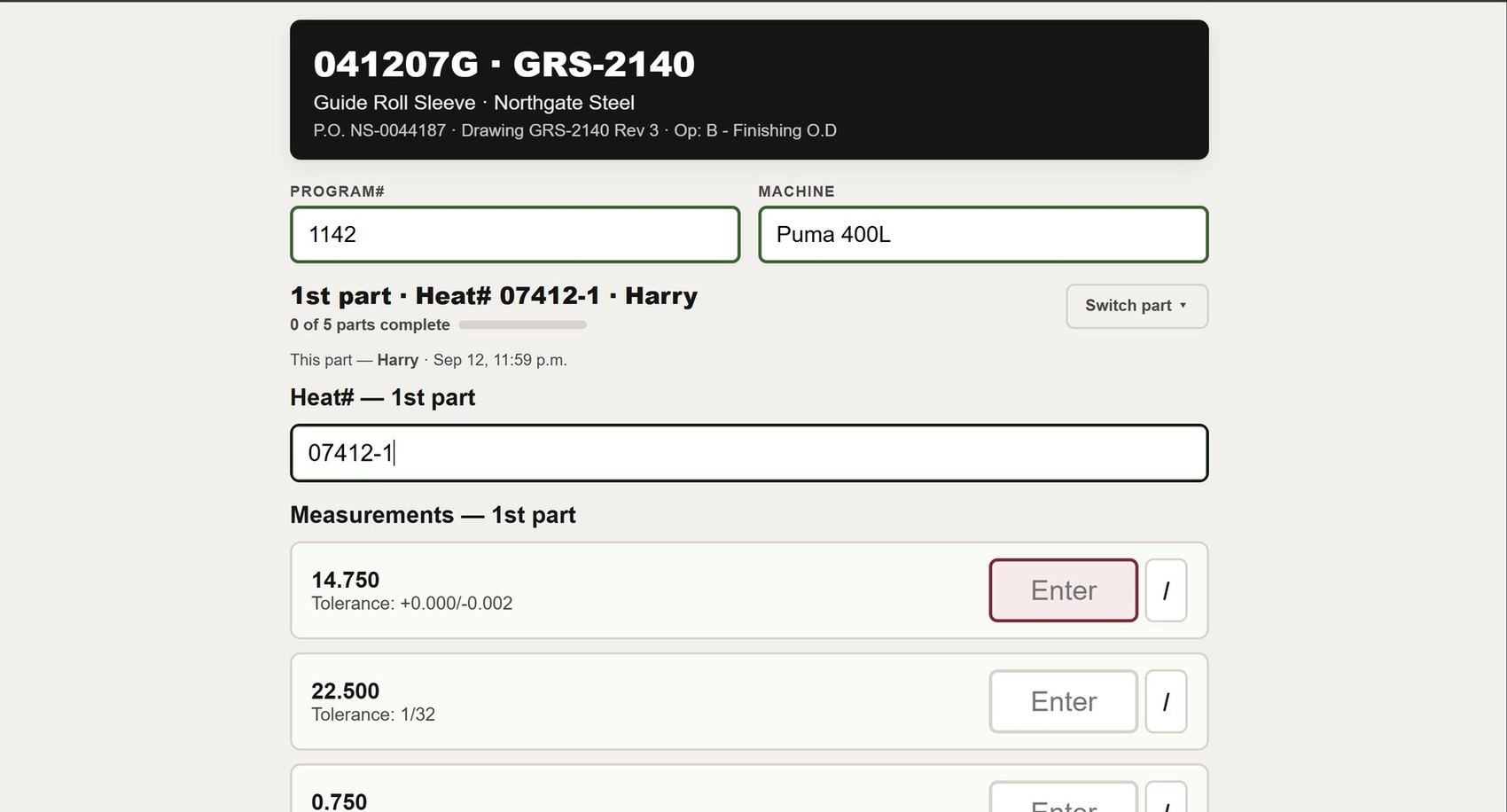
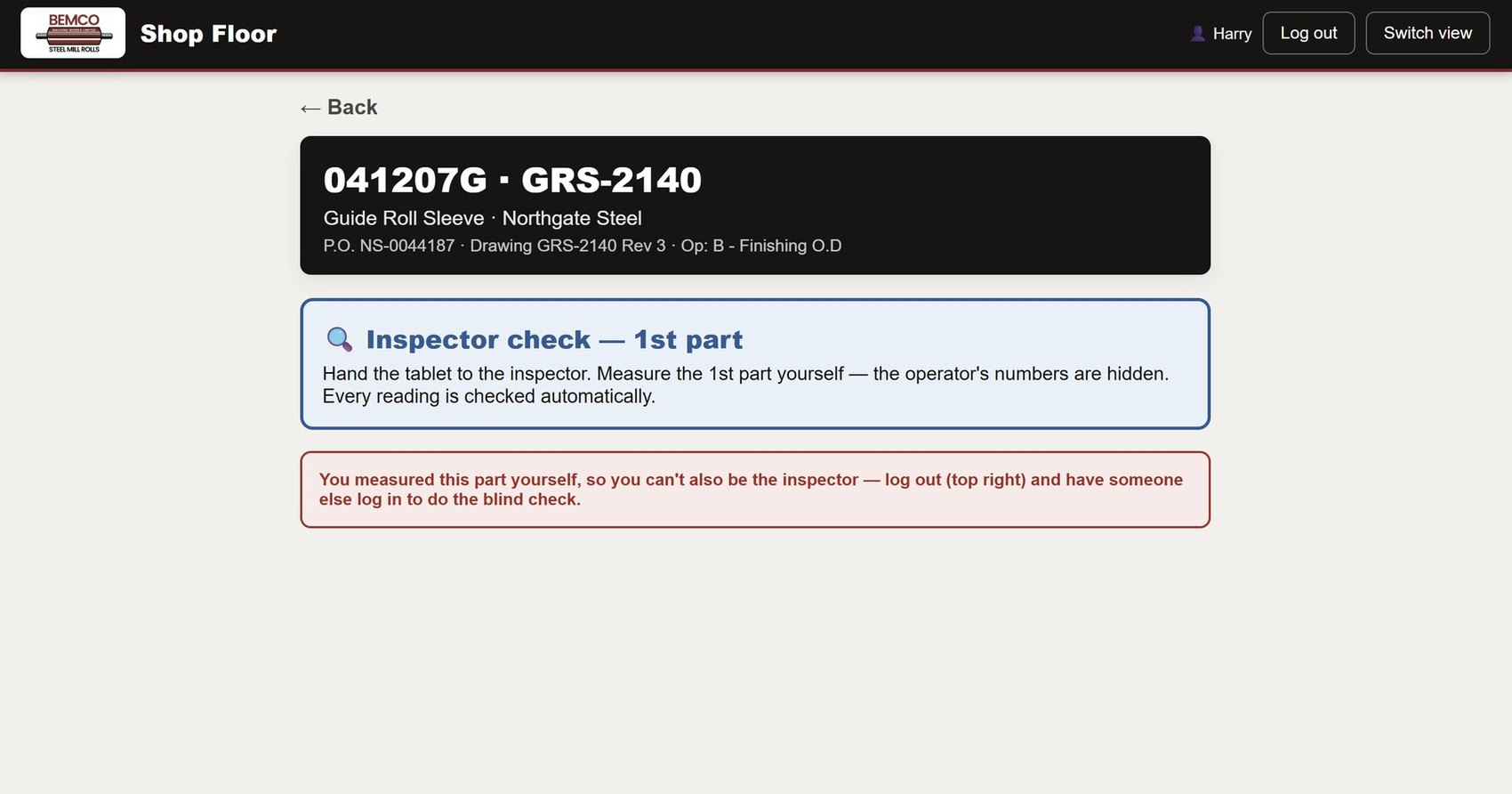
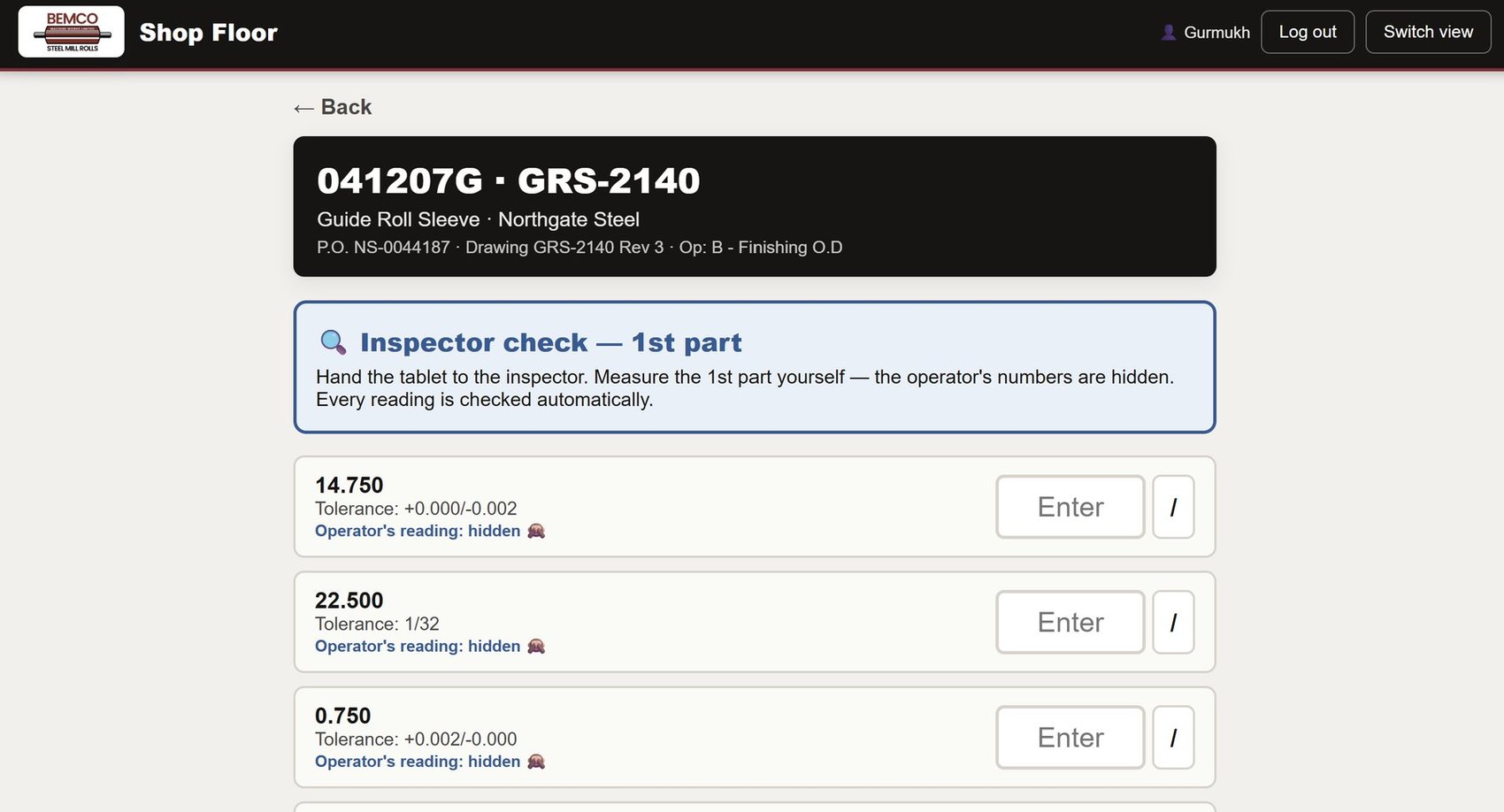
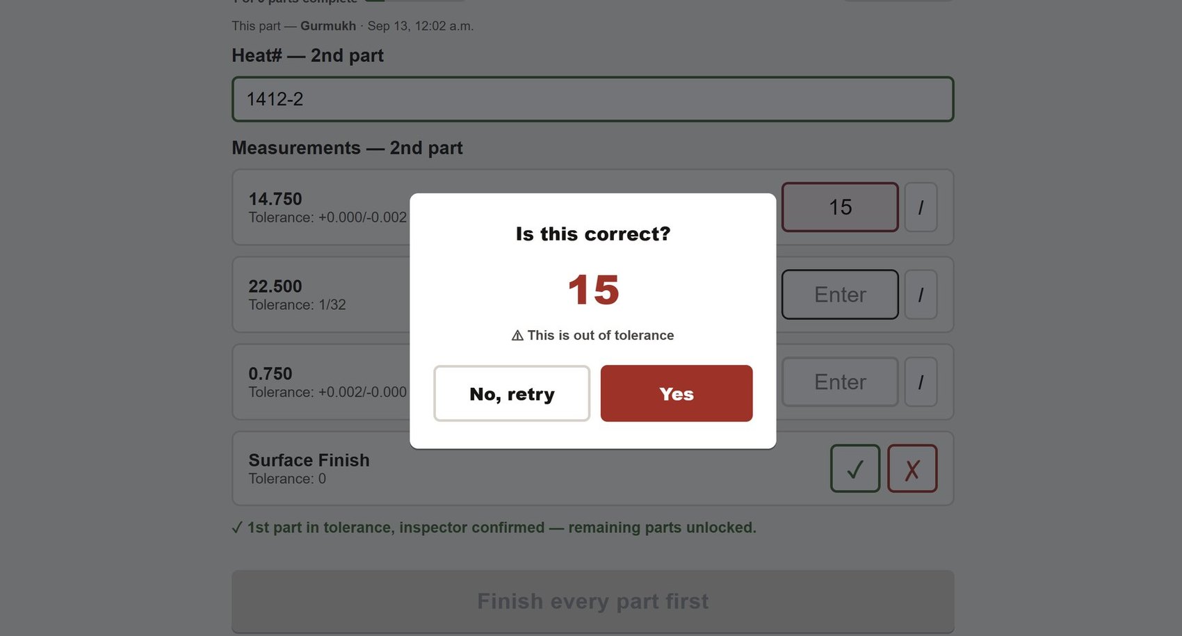
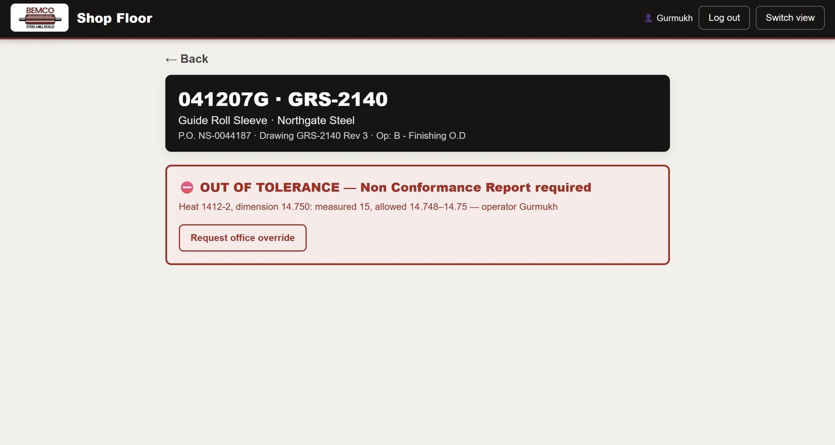
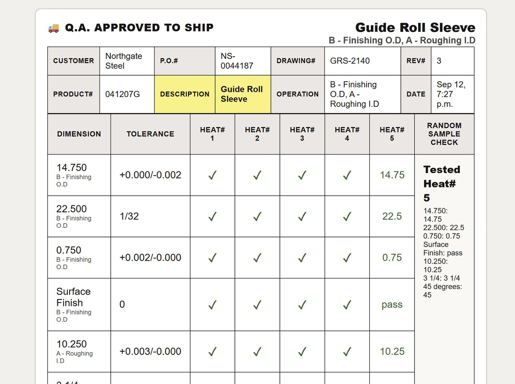
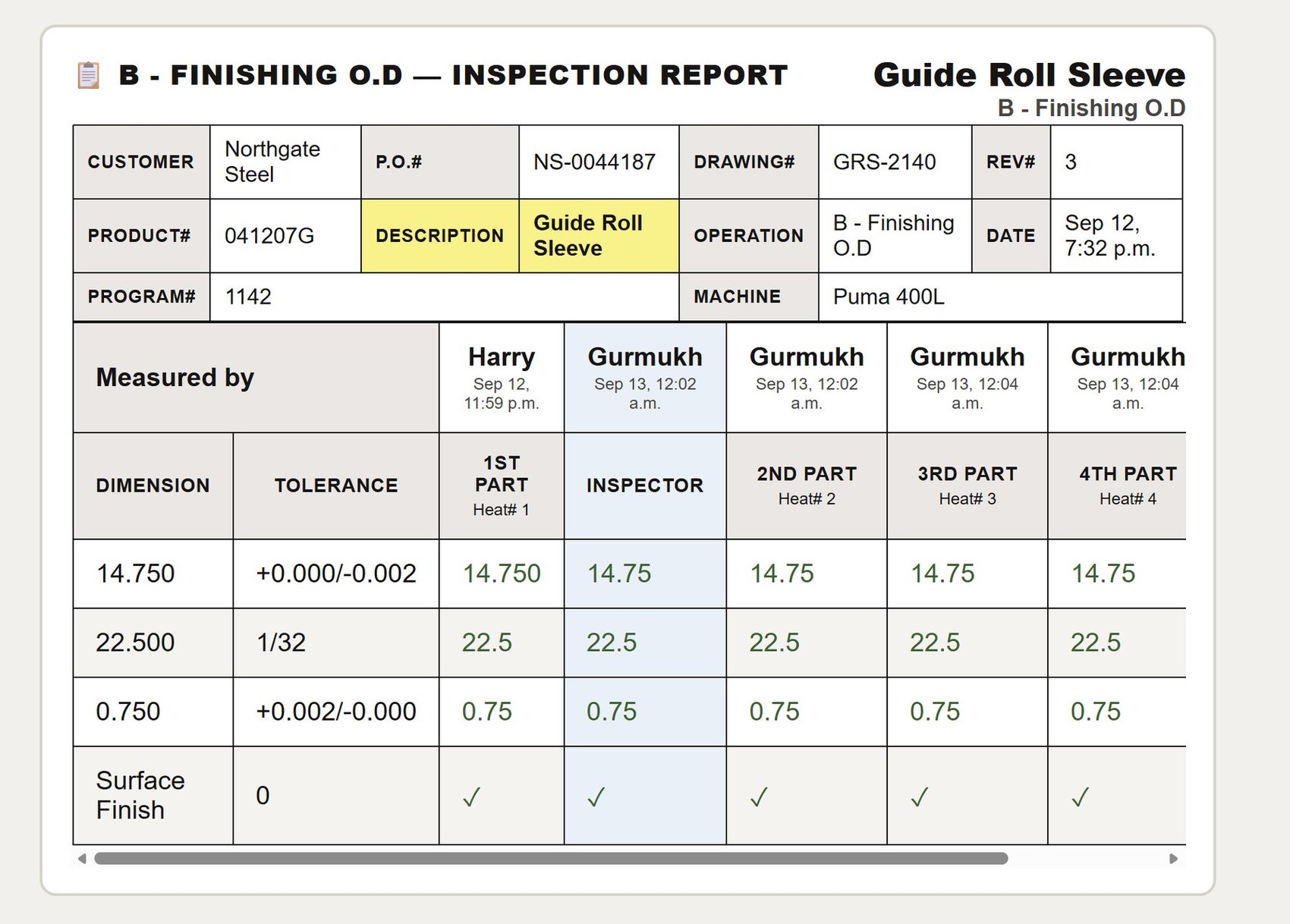
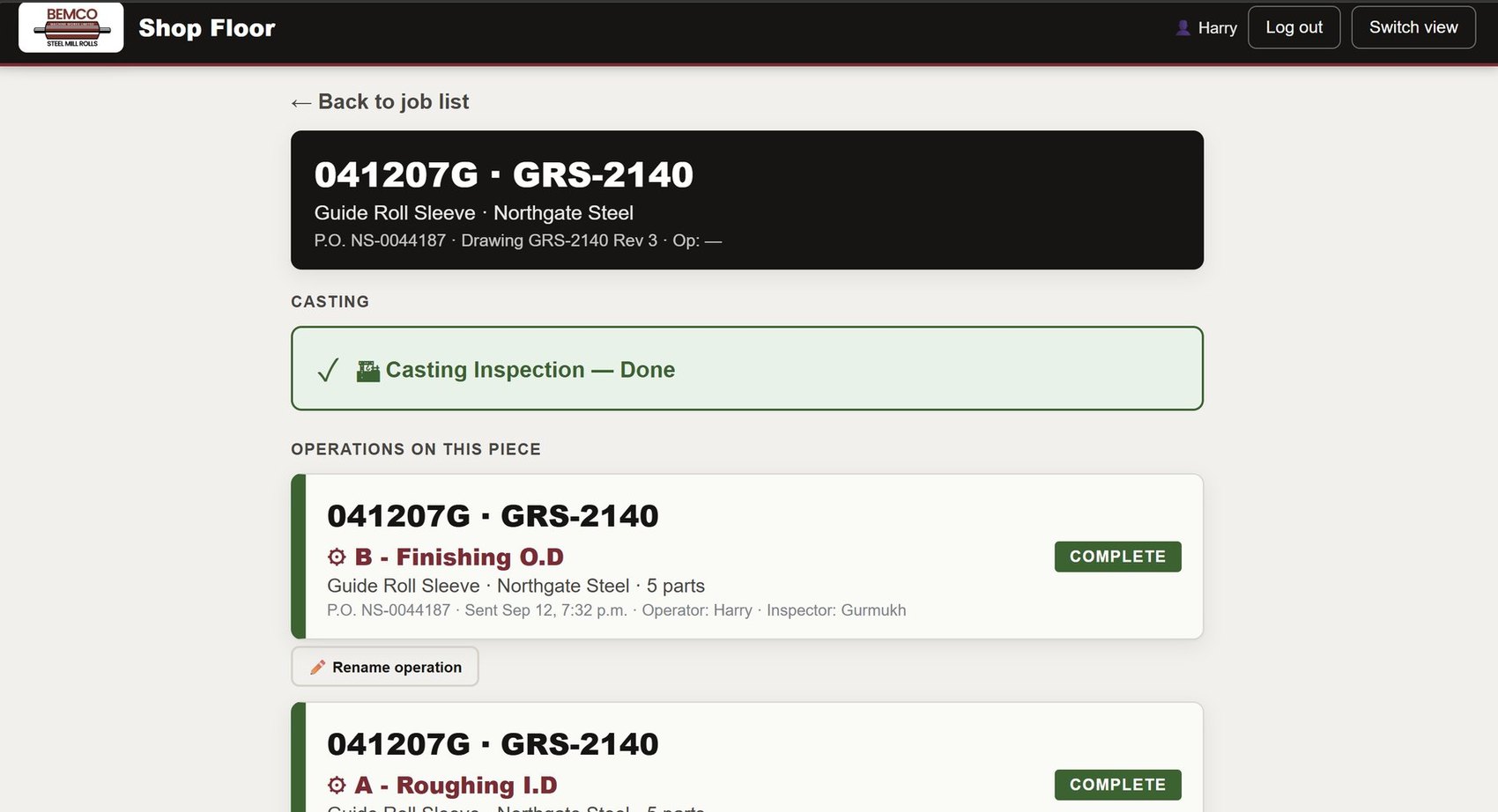
Screens shown use demonstration data. The same system is covered from the software side under Experience › AI & Software.
Retaining Wall
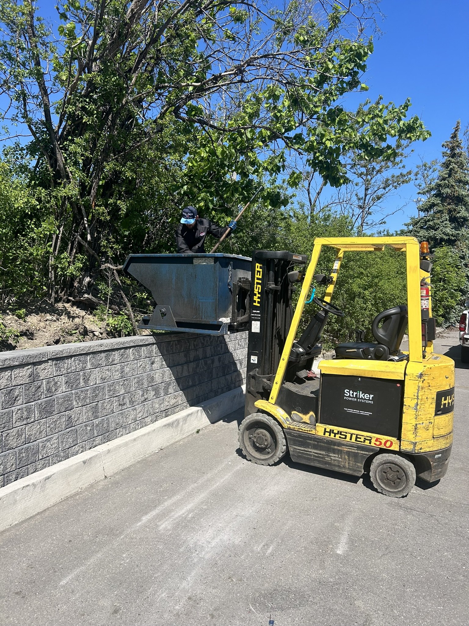
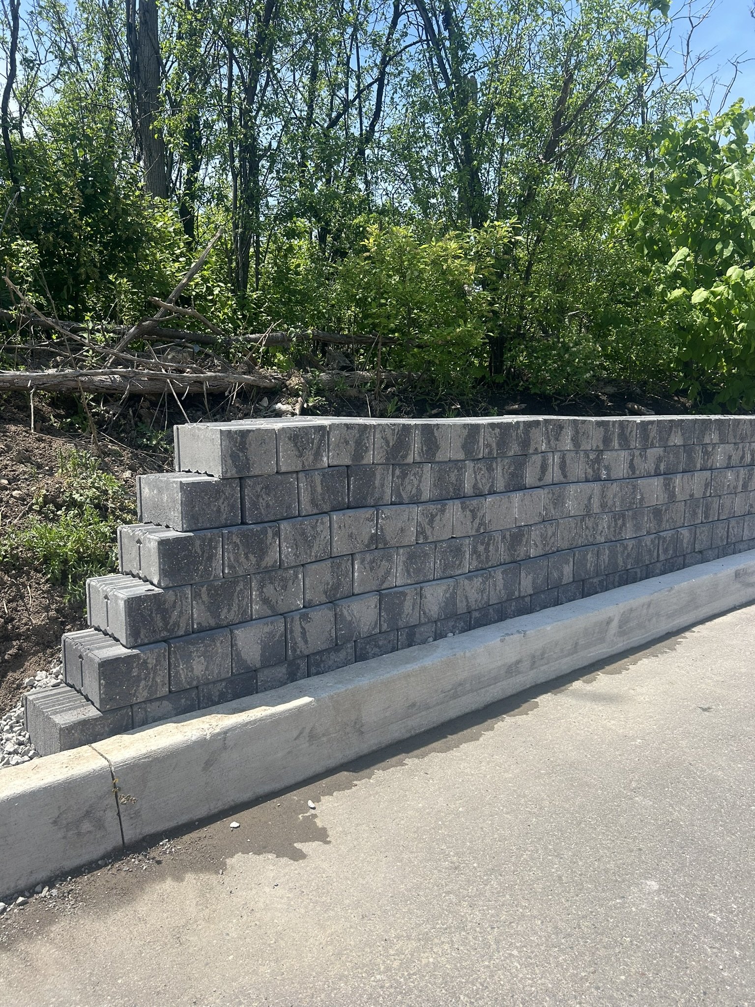
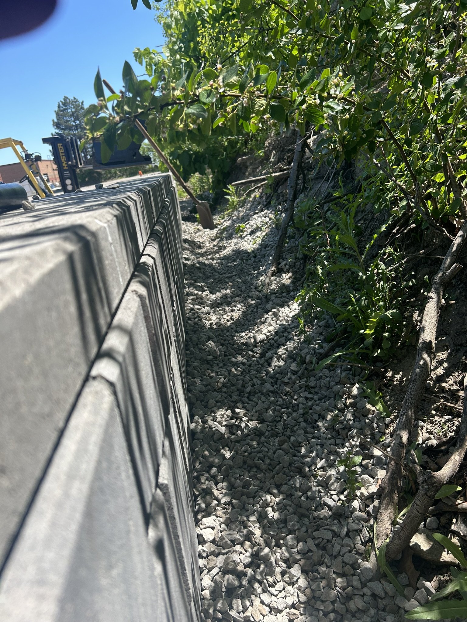
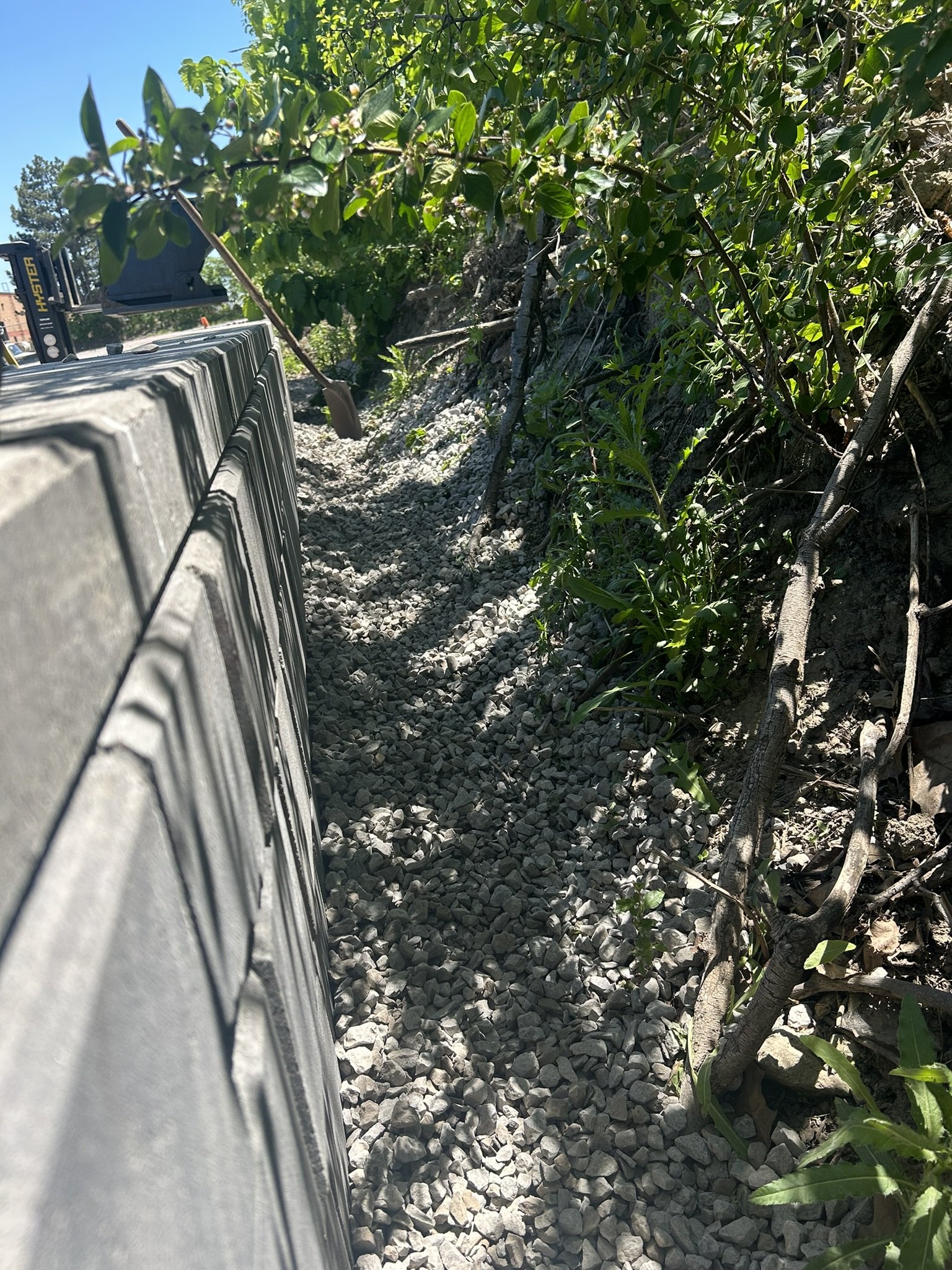
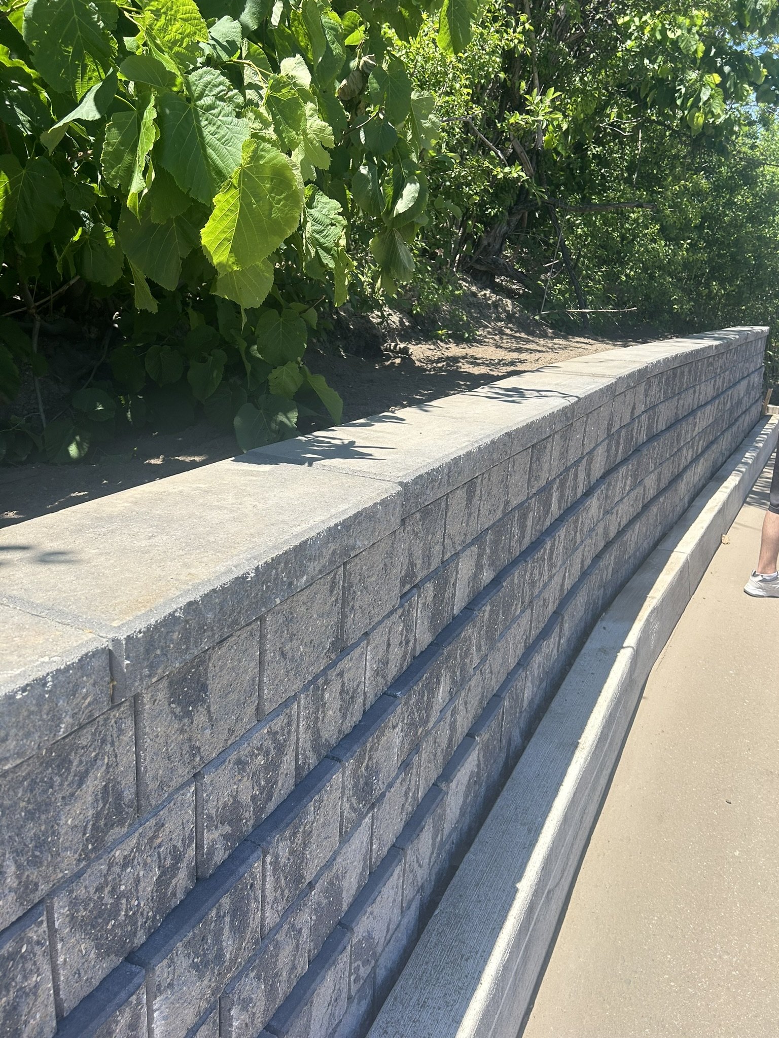
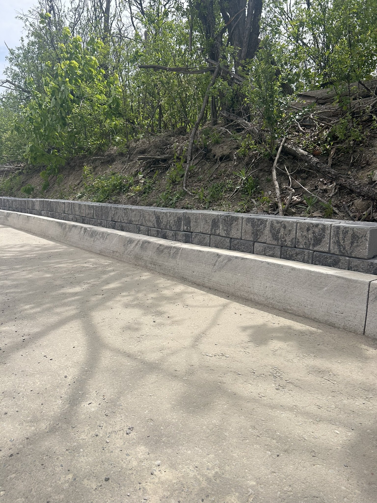
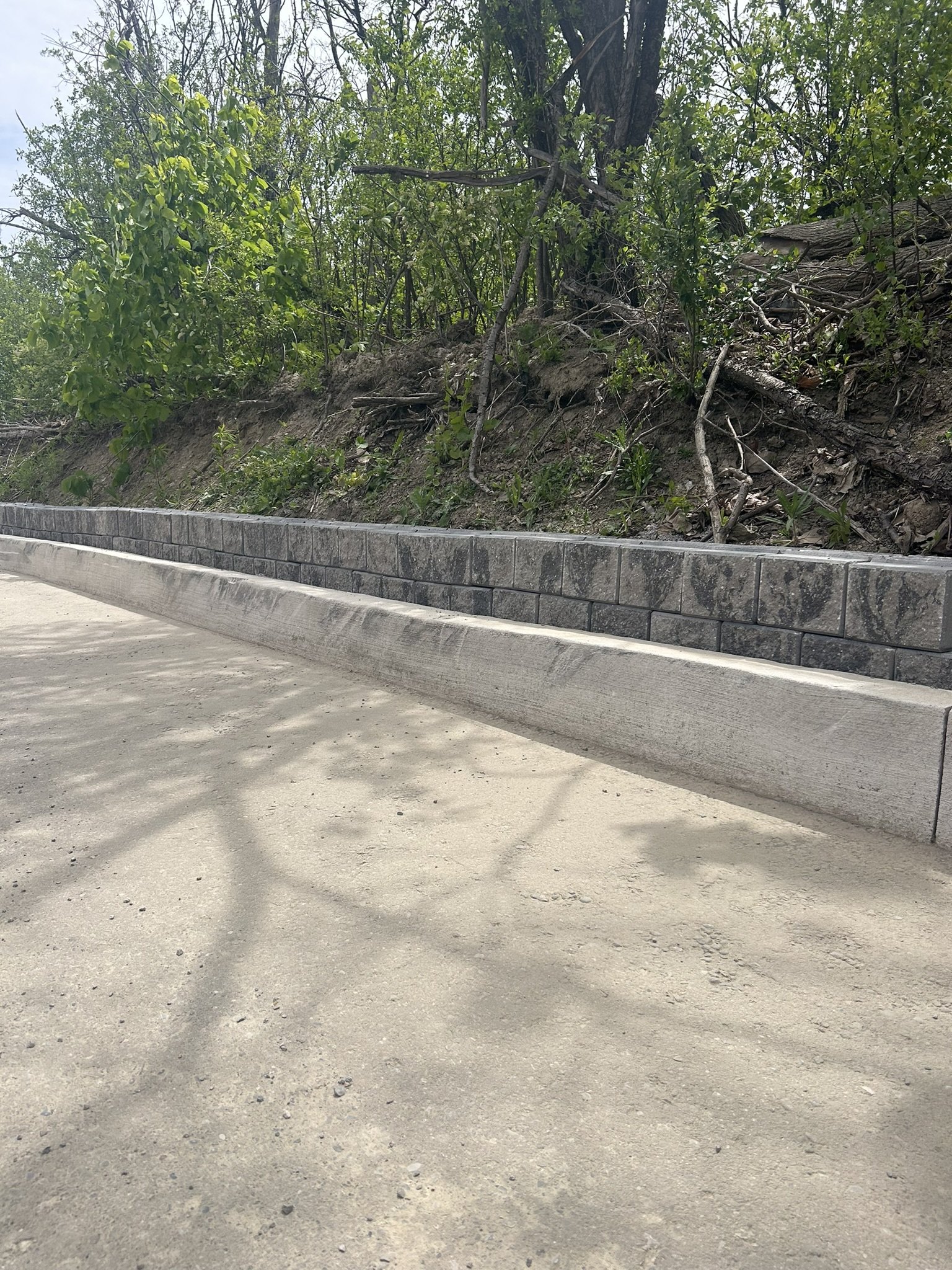
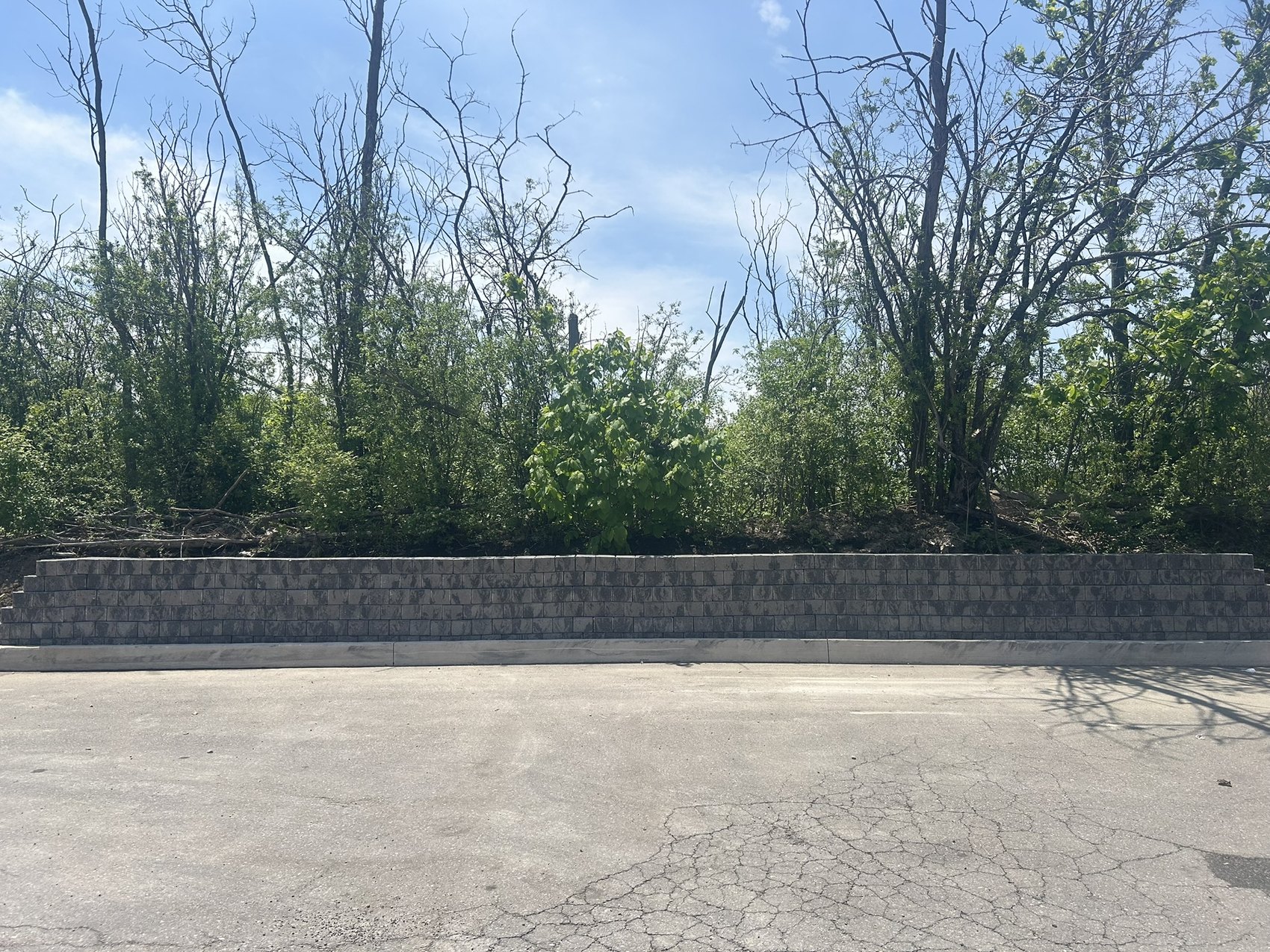
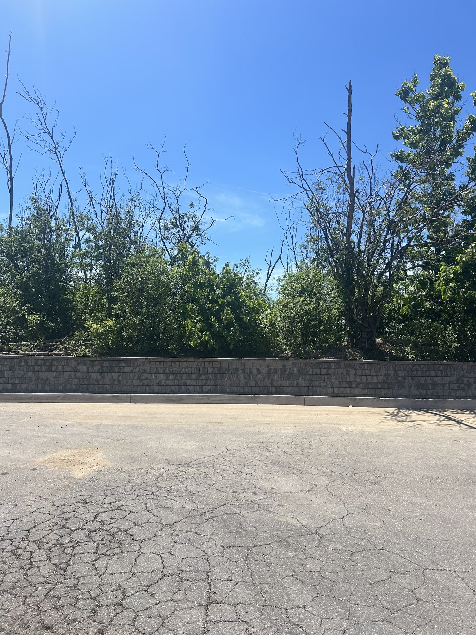
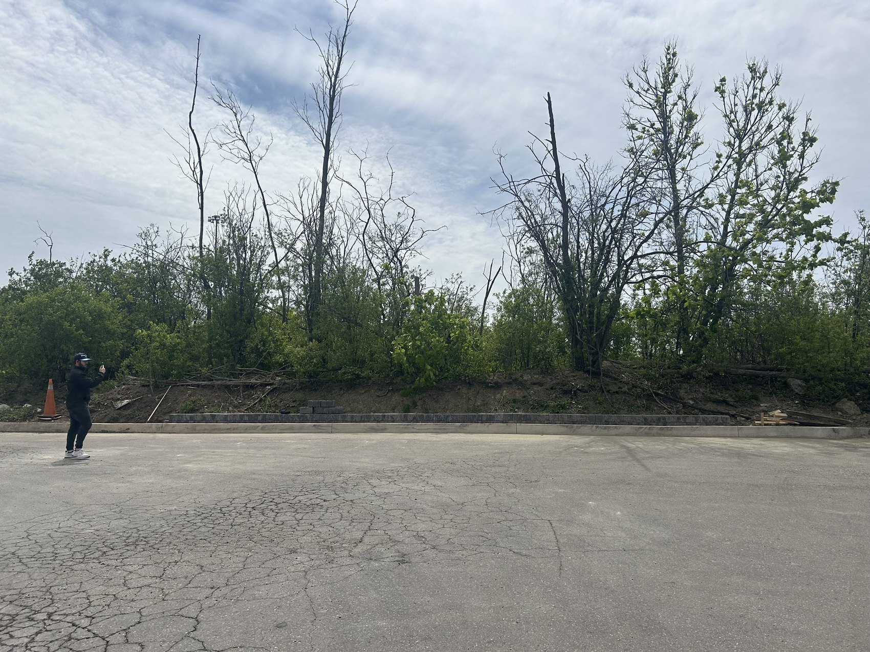
I designed and built a retaining wall sized to stop falling trees. The base excavation was set off the wall height, the gravel drainage layer runs to mid-height with a drain pipe to relieve water pressure behind it, and every second course is set back so the wall resists tipping.
Front Suspension Team (1st Place Overall OktoBAJAfest)
- Conducted design and manufacturing of the front suspension for an SAE Baja off-road vehicle by independently researching manufacturing methods and design trade-offs under competition constraints.
- Improved prior suspension design, contributing to 1st place finishes in Hill Climb (15.72 s), Short Track (24.32 s), Baja Cross (79.07 s), and Endurance under varied dynamic loading conditions.
- Redesigned and modeled suspension components in SolidWorks, including the spherical plain bearing (uniball), conducting iterative design refinement to optimize strength, manufacturability, and assembly integration.